


Ziroli 1/6 Hellcat Build
 12-04-2023, 02:23 PM
#326

Thread Starter
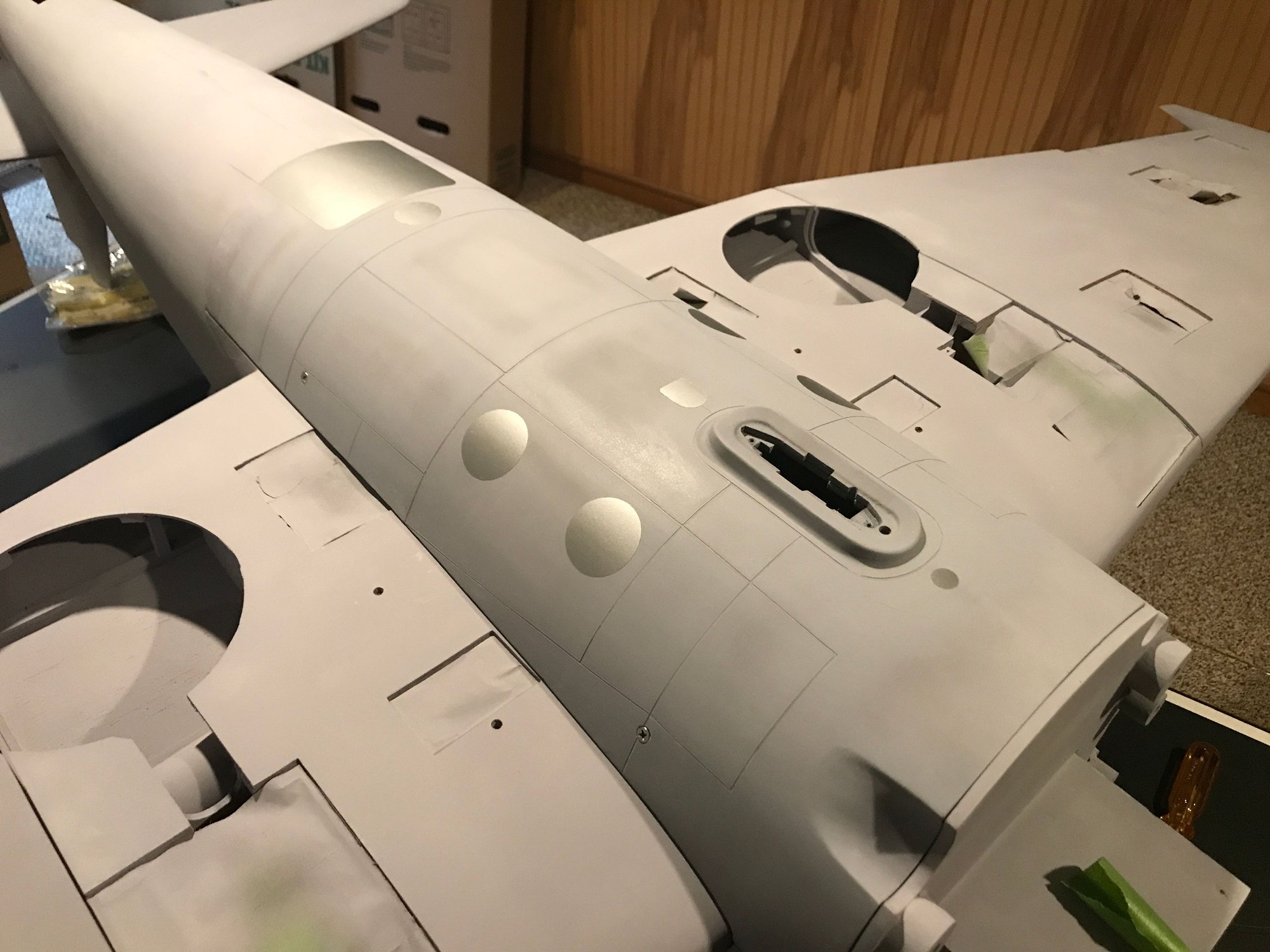
Belly pan panel lines and details from NS Modelers completed.
This was my first time creating panel lines. I used 1/32" ChartPak Graphic black tape. I also have 1/64" which might be more to scale. However, as this was my first attempt and I had read that 1/32" is easier to work with, I though starting with this on the belly pan would be good practice. Will I use 1/64" elsewhere? Maybe, if only for gaining additional experience.
I started with regular gray primer, as I had used this to avoid too much build up on the fabric covered control surfaces to avoid washing out the rib stitching and pinking tape edges. This worked very well on these surfaces, but not so well for the panel lines as the buildup was so minimal. I switched back to gray filler primer and that worked well.
I tried sanding the top of the tape before peeling it off, but was taking lots of time with little progress. As the belly pan was my first attempt at panel lines and probably the easiest part to repair if I made a mistake, I decided to just peel the tape off. I did this carefully, peeling the tape back over itself at almost 180 degrees. This worked perfect with no damage to any of the panel lines. I then lightly wet sanded the entire surface with 600 grit 3M sand paper to easy any sharp edges and to give the pan a uniform finish.
Hmm... Just had an idea. I think I'll make a cover for the fuel tank drop mech. for use when the drop tank is not installed. It will look less like a gaping hole once the drop servo is installed, but would look better, I think, with a cover. It could attach using a fitting similar to that used by the drop tank.
I'll probably move onto the wing center section, next and then the outer wing panels. These bits are smaller, less unwieldy, and all butt joints - easier to complete and will provide more practice before attacking the fuse and tail feathers. The fuse has many overlapping joints - I know how to create these, just not quickly. Maybe have the fuse all taped, spray the forward most section, remove the tape there after drying, spray the next section, remove the tape and so on until reaching the back of the fuse... Perhaps I could get 3 coats on at each panel overlap and finish the process in a day?
Belly pan panel lines and details
 12-05-2023, 03:32 PM
#327
Thread Starter
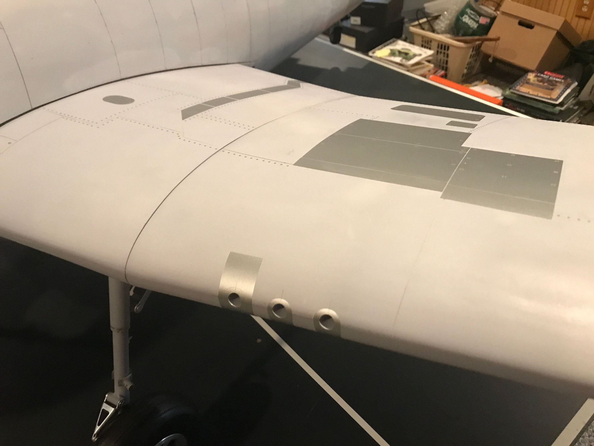
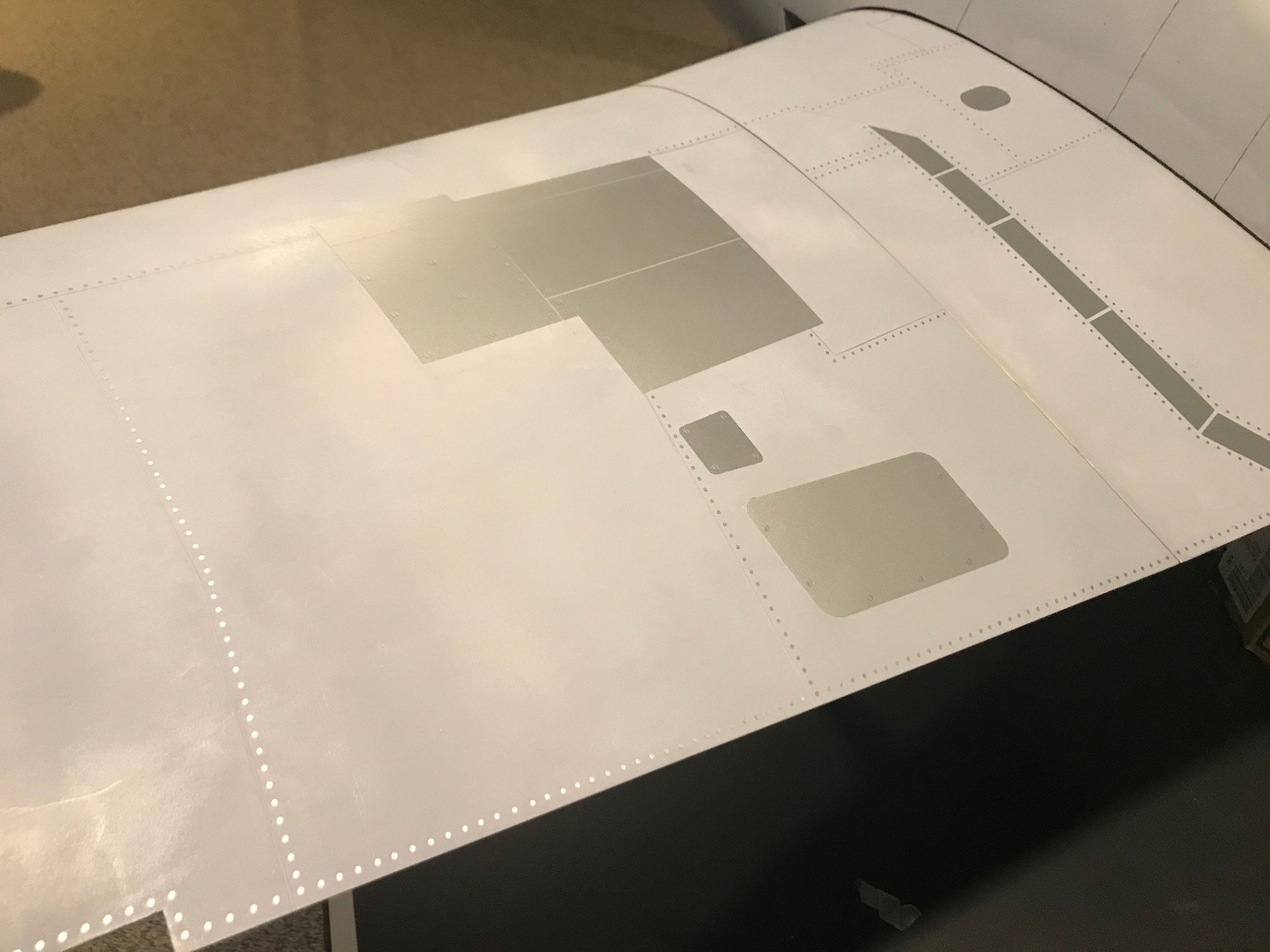
Rivets! Almost forgot these. A quick review of Mirce's pics and some online Hellcat pics showed that yes, the belly pan gets its share of rivets.
For now, just a picture of how this is starting to look. I'll post something when the pan is done, but it may be awhile.

Starting to apply rivet details
For now, just a picture of how this is starting to look. I'll post something when the pan is done, but it may be awhile.
Starting to apply rivet details
12-09-2023, 10:12 AM
#329
Junior Member
Join Date: Oct 2023
Location: Devon, UK
Posts: 9
Likes: 0
Received 0 Likes
on
0 Posts
Hi Dale. I think I might have replied via email. I,m on a Hughes H-1. The plans didn't quite work (trying to make as true to full size as possible). Very hard to conceal the rudder and elevator controls. Now little space. Spent a bucket on bits of tail wheel, trying to create something that will work..
12-09-2023, 10:41 AM
#330
Thread Starter
The kit for the Hellcat came with 2.25k rivets and I'm already 1/3 the way through them. So, I'm ordering another 10k from Mirce. I'll probably have a few leftover, but I don't want to be caught short
In parallel, I'm refurbishing the Robart 150 GS retracts. Even these are getting old at 20+ years!
EE Michigan Tech, '85. My Lord, how time flies...
Last edited by DaleCS; 12-09-2023 at 10:42 AM. Reason: Missed a word
12-09-2023, 11:05 AM
#331
Thread Starter
Hi Dale. I think I might have replied via email. I,m on a Hughes H-1. The plans didn't quite work (trying to make as true to full size as possible). Very hard to conceal the rudder and elevator controls. Now little space. Spent a bucket on bits of tail wheel, trying to create something that will work..
I did not see an email from you, and I checked my spam folder, too.
There are some threads on RCU about hidden rudder controls. Have you seen any of them? Here's one: Hidden rudder control
I've have a Patriot 40 dressed as a Marine T-45 Goshawk that uses the rudder technique in this thread. .40 size, there's not much room. I'd like to show you the linkage, but it's buried in the tail. I'm trying to remember how I assembled it all...magic? I may have covered the fin and rudder before assembly to the fuse and before completion of the fuse sides or bottom, in order to have access to the rudder linkage.
Odd, RCU won't let my post a picture in this reply, even though I click on 'go advanced.'
Last edited by DaleCS; 12-09-2023 at 11:06 AM. Reason: Spell check
12-14-2023, 08:19 AM
#332
Thread Starter
Hi Dale. I think I might have replied via email. I,m on a Hughes H-1. The plans didn't quite work (trying to make as true to full size as possible). Very hard to conceal the rudder and elevator controls. Now little space. Spent a bucket on bits of tail wheel, trying to create something that will work..
Switched browsers and the ability to attach pictures works, here.
Rudder, elevator and (not shown) aileron controls on the Patriot 40 are all internal. Using SpringAir retracts, though this does use a nose gear. A retractable tailwheel would be a tight fit in such a plane (and wouldn't work well as the mains would need to be moved forward and inboard, plus the idea of a tailwheel retracting into a jet engine, even if a dummy one, is just wrong!), but I can envision taking a stock, non-retractable tail wheel and making a custom, pivoting mount for it.
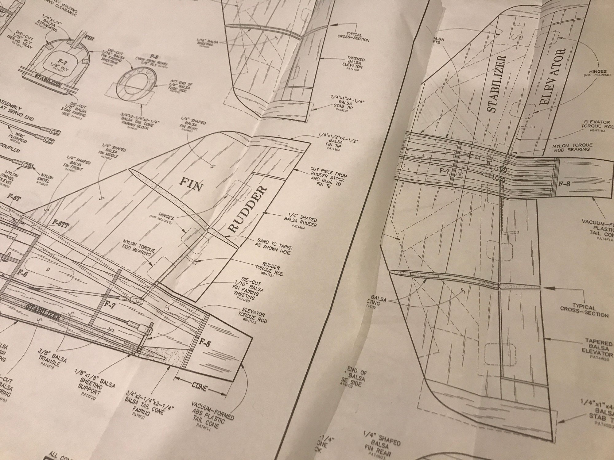
Patriot 40 drawings showing internal controls for rudder and elevator. Not shown - aileron controls are also internal.
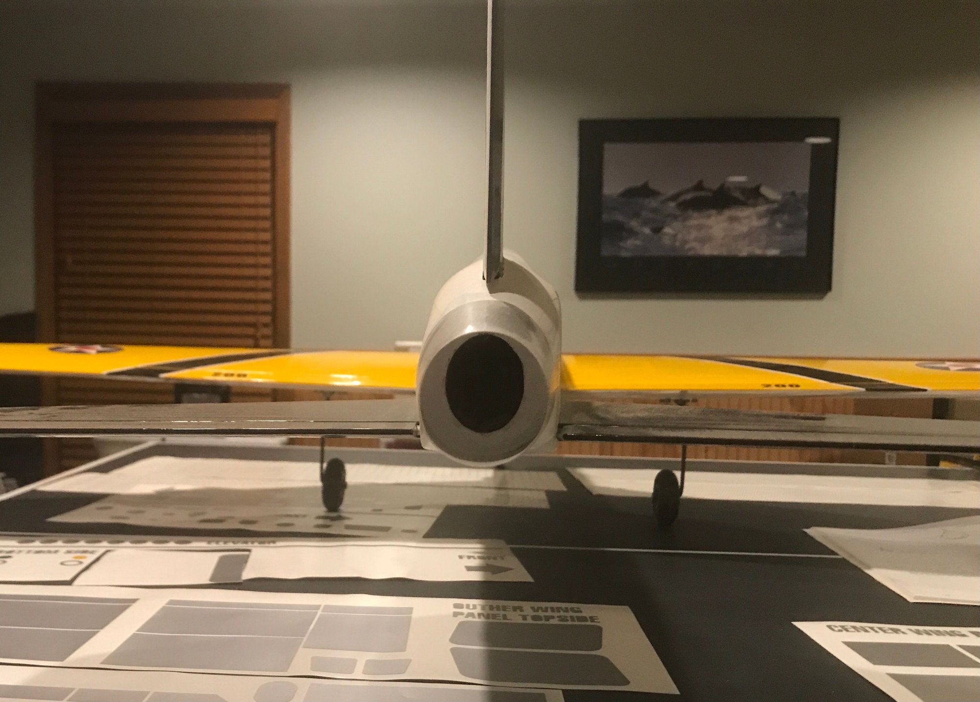
Tail view - no external controls!
12-18-2023, 09:26 AM
#333
Thread Starter
Bell pan complete after almost 1200 rivets...
After painting, in the future, I'm now thinking of using a metal foil product for the exhaust indentations. A problem for another day.
Also, I rebuilt the landing gear (cleaned, new seals, greased and painted), plumbed airlines and installed. Hopefully, this is the final install. I also picked up a Robart #176 Pressure Guard. I had one belly landing with the previous Hellcat due to a slow leak. This device may not provide protection in all scenarios, but hopefully the most likely scenarios. Looking forward to testing it.
12-19-2023, 09:03 AM
#335
Thread Starter
12-22-2023, 12:25 PM
#336
Thread Starter
Tried establishing overlapping panel lines on the fuse with a tape measure and drafting aids. I quickly realized how valuable a cross-line laser could be. I took Chad's encouragement regarding this value and bought a Bosch GLL30S from Home Depot.
As my local store was out, I ordered on line and had it delivered, next day. Very good, except I don't understand why the lasers are behind locked gates at HD, but show up on one's doorstep in the OEM's display box. No shipping wrap, no plain cardboard box - very easy to see what's inside, asses the value and steal if so inclined! Glad we were home to grab it as soon as it was placed on the porch. First time using HD delivery. Lesson learned.
This is a 635nm, <1mW laser, Class 2, a low power laser. I'm not a laser expert. Please, read the instructions, do your own research on laser hazards, eye safety and make your own decisions. I learned some stuff. You may too!
Using drawings, I found that the overlapping panel lines are parallel with the trailing edge of the vertical fin (fin, not the rudder!). I squared this edge up with the vertical line of the laser and marked a horizontal reference line and marked the position of the most rearward overlapping panel line. I then moved the laser horizontally to the left, not rotating it, but actually picking it up and moving it left to align its vertical line with the overlapping panel line already completed on the belly pan. One must move the the laser in order to maintain straight, vertical lines on the fuse. If one leaves the laser in place and just rotates it, one will get some really interesting non-scale, panel line curves!
The laser line width is about 2.5mm with the laser setup about 6' from the model. It's important when marking the model to consistently use one side of the beam.
Before going farther, I think I'll repeat these steps on the opposite side of the fuse in order to see how well I can get the vertical panel lines on each side of the fuse aligned with each other.
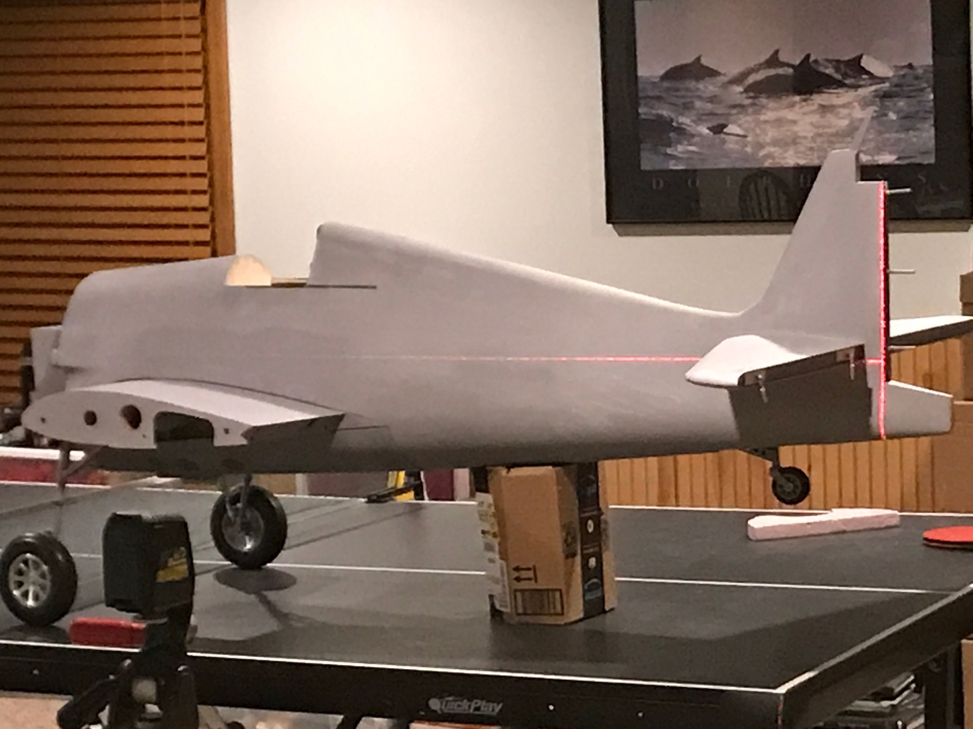
Establishing reference coordinates and most rearward overlapping panel line

Locating overlapping panel line shared between fuse, wing center section and belly panel. Note that the windows are covered to prevent the laser from hitting my neighbors!
As my local store was out, I ordered on line and had it delivered, next day. Very good, except I don't understand why the lasers are behind locked gates at HD, but show up on one's doorstep in the OEM's display box. No shipping wrap, no plain cardboard box - very easy to see what's inside, asses the value and steal if so inclined! Glad we were home to grab it as soon as it was placed on the porch. First time using HD delivery. Lesson learned.
This is a 635nm, <1mW laser, Class 2, a low power laser. I'm not a laser expert. Please, read the instructions, do your own research on laser hazards, eye safety and make your own decisions. I learned some stuff. You may too!
Using drawings, I found that the overlapping panel lines are parallel with the trailing edge of the vertical fin (fin, not the rudder!). I squared this edge up with the vertical line of the laser and marked a horizontal reference line and marked the position of the most rearward overlapping panel line. I then moved the laser horizontally to the left, not rotating it, but actually picking it up and moving it left to align its vertical line with the overlapping panel line already completed on the belly pan. One must move the the laser in order to maintain straight, vertical lines on the fuse. If one leaves the laser in place and just rotates it, one will get some really interesting non-scale, panel line curves!
The laser line width is about 2.5mm with the laser setup about 6' from the model. It's important when marking the model to consistently use one side of the beam.
Before going farther, I think I'll repeat these steps on the opposite side of the fuse in order to see how well I can get the vertical panel lines on each side of the fuse aligned with each other.
Establishing reference coordinates and most rearward overlapping panel line
Locating overlapping panel line shared between fuse, wing center section and belly panel. Note that the windows are covered to prevent the laser from hitting my neighbors!
12-26-2023, 04:11 PM
#337
Thread Starter
[QUOTE=DaleCS;12790582]Using drawings, I found that the overlapping panel lines are parallel with the trailing edge of the vertical fin (fin, not the rudder!).
After laying out the markings for the vertical overlapping panel lines on the right side of the fuse, it was just off a bit. Rechecked the drawings, got out my drawing triangle tools and yes, I was wrong. The trailing vertical fin edge is NOT parallel to these panel lines. Close, but not close enough.
More checks, and I've settled on using the rear panel of the cockpit. A few lines marked and drawn and it's looking much better. A couple of degrees makes a difference.
12-28-2023, 06:55 AM
#338
My Feedback: (23)
Dale, I believe I did the same thing. Used the end of the cockpit and then transferred the ratios from a plastic model and worked the scale out. A nightmare! Check it to your results. I did the best I could with what I had. I wasn�t trying to win Top Gun or anything, just wanted it to be a nice job. Showed my father in law, he said, �Don�t fly it you will crash it�. He has passed away a few years ago. I had the airplane for sale but that�s not going to happen. I will fly it when I retire. I won�t crash it because he�s looking over me.
Last edited by ledd4u; 12-28-2023 at 06:59 AM.
12-28-2023, 11:49 AM
#339
Thread Starter
Dale, I believe I did the same thing. Used the end of the cockpit and then transferred the ratios from a plastic model and worked the scale out. A nightmare! Check it to your results. I did the best I could with what I had. I wasn�t trying to win Top Gun or anything, just wanted it to be a nice job. Showed my father in law, he said, �Don�t fly it you will crash it�. He has passed away a few years ago. I had the airplane for sale but that�s not going to happen. I will fly it when I retire. I won�t crash it because he�s looking over me.
I hope your father-in-law is waiting to say, "Great job!" and not, "I told you so!" We're building planes, not models. Planes fly, models set. I think we'll both do everything we can to reduce risks. And that's all you can do, while enjoying the process.
Looking forward to your first flights pictures.
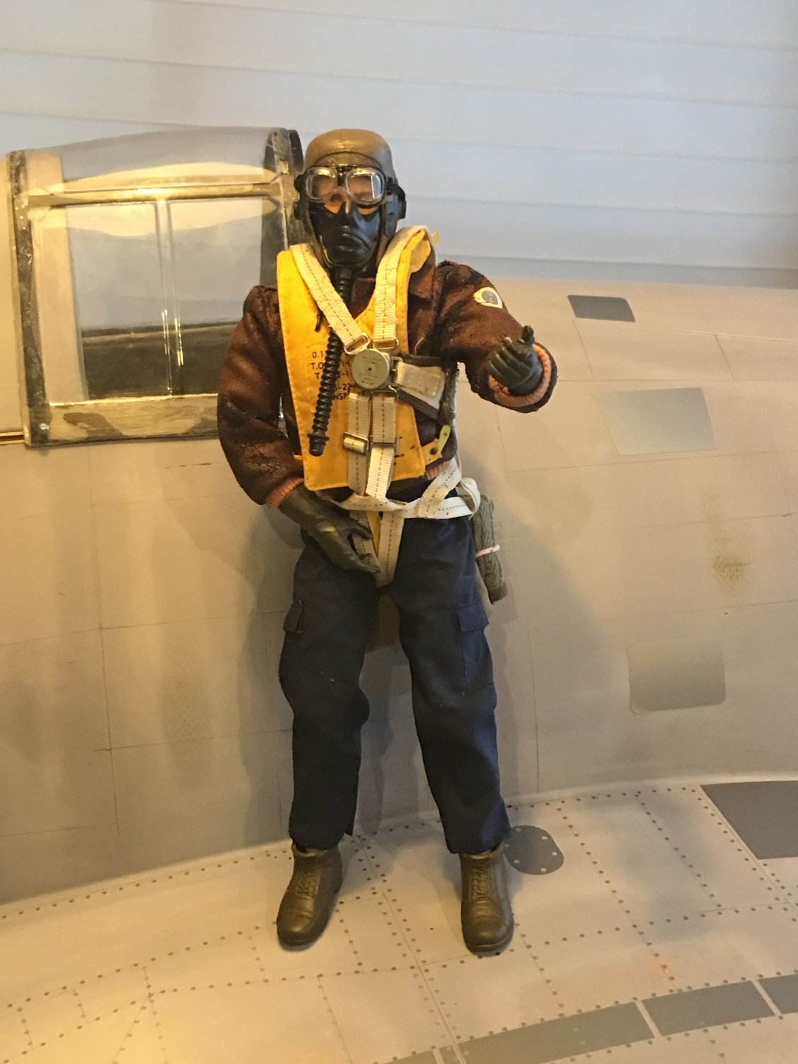
BTW: Your pilot figure is excellent. Do you mind if I ask where you find it? I have a nice one, but it is headless... We searched and searched, but it is a feature now hidden in a cornfield outside Lansing, MI.
12-30-2023, 11:17 AM
#341
Thread Starter
My former pilot was from Blue Box. I see that there are some navy WWII versions available, but only the George Bush version - he didn't fly Hellcats. The WBP version looks like it may be lighter, which would be a good thing.
01-26-2024, 10:24 AM
#342
Thread Starter
All panel lines drawn. Except that after reviewing various pictures of full-scale Hellcats, my own and those from the internet, I was confident that I didn't have the full details - the drawings and pictures I had were incomplete and the online pictures either didn't include sections I needed, or the resolutions were not adequate to see details. So, I picked up a 1/48 scale Eduards kit. I'll be using this to confirm what I have drawn, add some bits and remove a couple lines which aren't supported by pictures or the kit. Not going for museum quality, but if there is something not documented, I don't want to waste effort putting it in, and I'd rather spend my time adding any bits which I think add more interest. Will I build the plastic kit? Perhaps AFTER I get the big bird done!
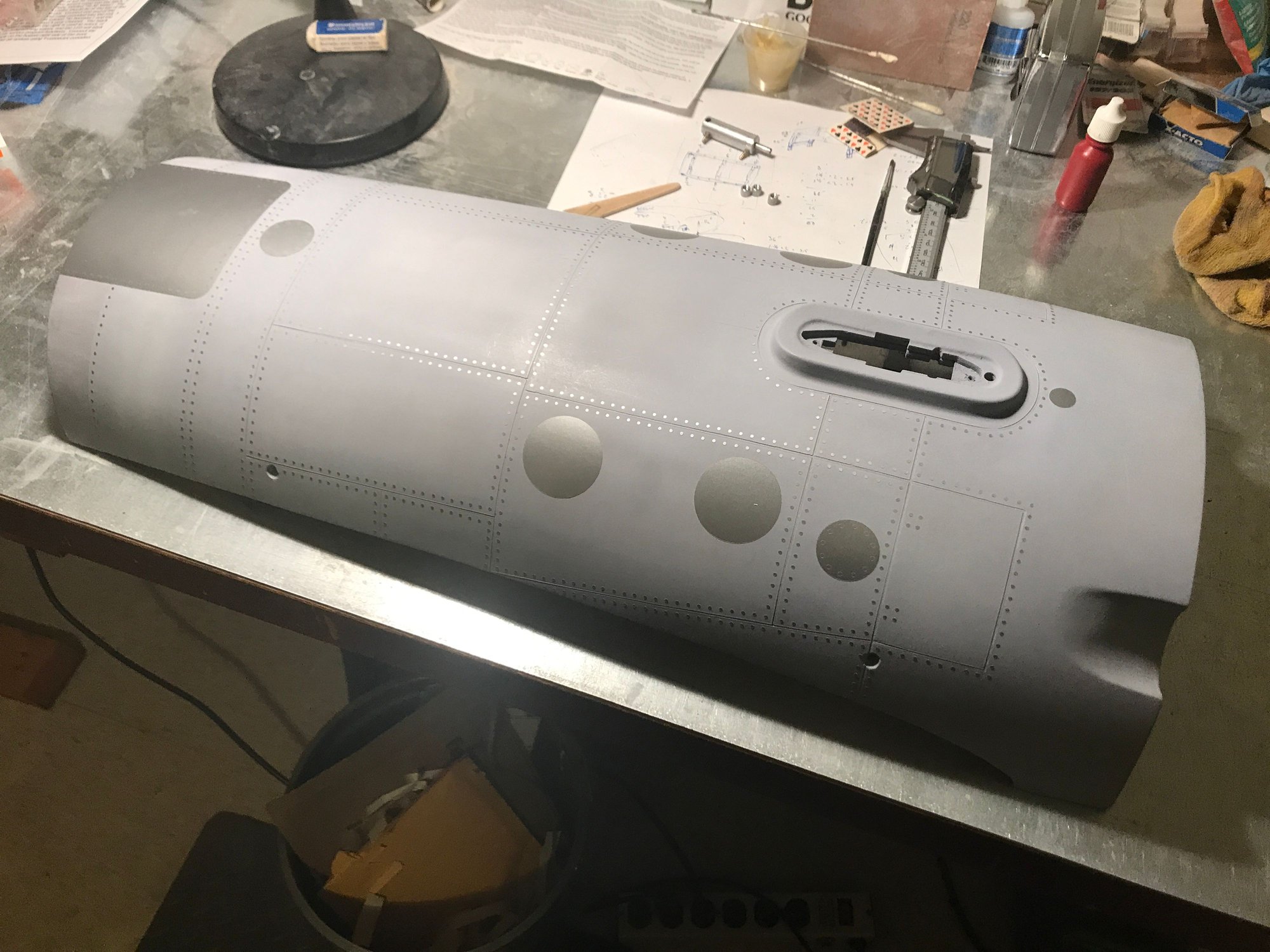
While waiting for the Eduards kit, I sanded off the raised paint lines on the cowling, created by the tri-color paint scheme applied by Top-Flite. When going through the prime/sand process, I added a well documented panel line to the top of the cowling. Then, added the dummy screw head details from NSModelers. The Hellcat detail kit came with 5 different types of dummy screws - 3 different diameters of which 2 had different center to center spacing. The cowling appeared to need the most amount of dummy screws, so I measured the total linear distance to be covered and then used the center to center spacings of the 5 types to determine that I'd need about 260 or more dummy screws to complete the cowling. The 3.3mm diameter dummy screws came in a group of 294, so I chose these for the cowling. The other screw groups all had 194 or fewer and should be more than enough to finish the rest of the plane.
Why go into this? Well, I made a mistake not noticing the different center to center spacing. I put over 30 dummy screws on the cowling before noticing the spacing differences and determining that I would not have enough of the selected type to complete the cowling with a uniform set of dummy screws. Could I have made this still work? Perhaps with manually spacing pieces from other types. Would I run out of the other types on other sections of the plane, cascading the problem? Perhaps. Did the cowling use different size/spacing screws in real life? I don't know, couldn't find info and wasn't driving back to Kalamazoo to find out. I decided to test using scotch tape to remove the dummy screws that I had applied and see if I could save them for later use. As this went much easier than anticipated, I decided to complete the removal and start the process over. The picture below shows the results using the 3.3mm dummy screws. I'm happy.
A few more dummy screws to apply to the cowling and it will be done, except for adding a dummy cooler in the chin. I think I'll do the panel lines and rivet/screw/panel details on the wing center section, next. All butt panel joints and not many of them - easy-peasy.
That's all for today.
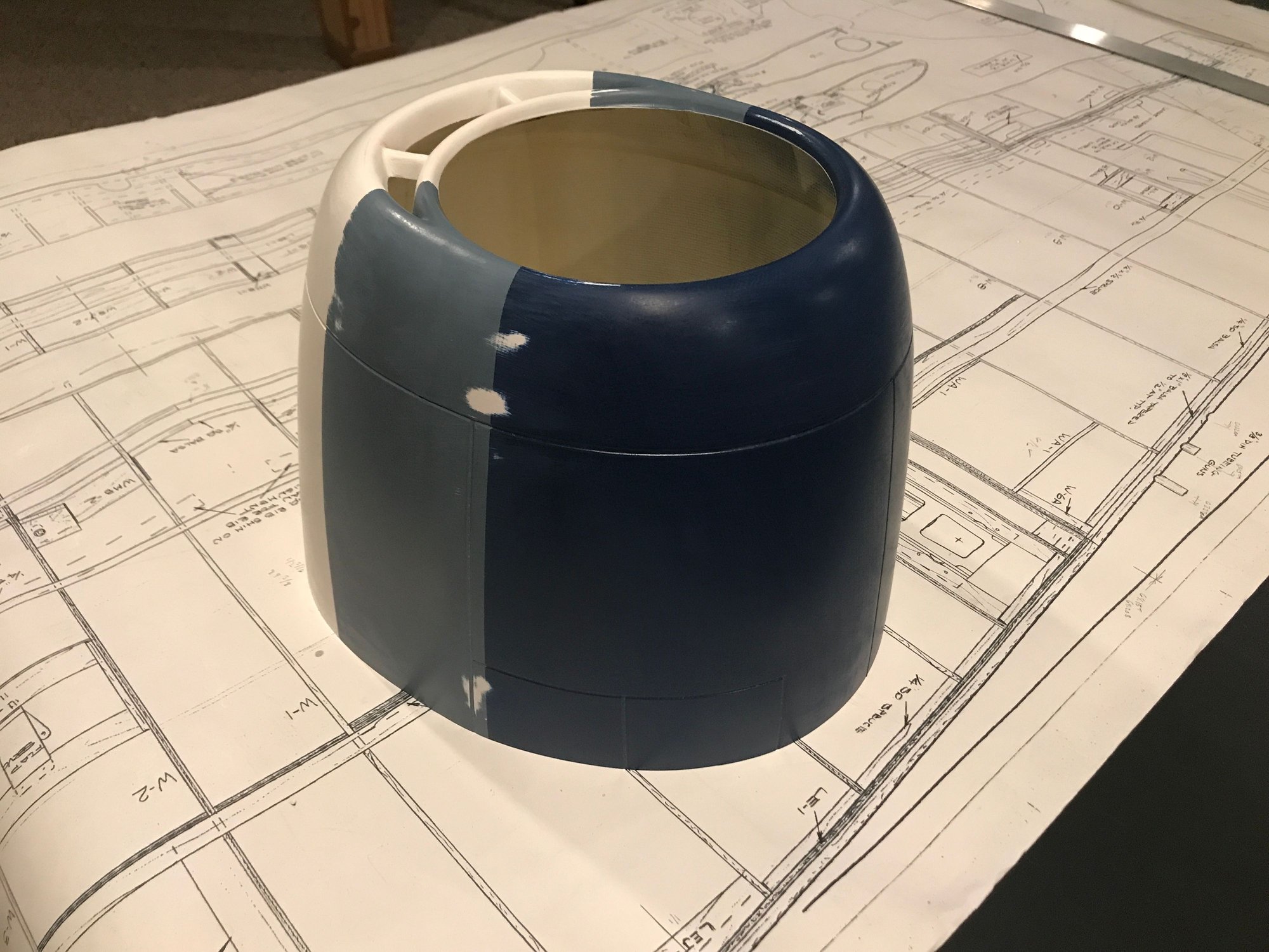
Original tri-color scheme, sanded, ready for primer.

Primed, wet-sanded and dummy screw details going on.
While waiting for the Eduards kit, I sanded off the raised paint lines on the cowling, created by the tri-color paint scheme applied by Top-Flite. When going through the prime/sand process, I added a well documented panel line to the top of the cowling. Then, added the dummy screw head details from NSModelers. The Hellcat detail kit came with 5 different types of dummy screws - 3 different diameters of which 2 had different center to center spacing. The cowling appeared to need the most amount of dummy screws, so I measured the total linear distance to be covered and then used the center to center spacings of the 5 types to determine that I'd need about 260 or more dummy screws to complete the cowling. The 3.3mm diameter dummy screws came in a group of 294, so I chose these for the cowling. The other screw groups all had 194 or fewer and should be more than enough to finish the rest of the plane.
Why go into this? Well, I made a mistake not noticing the different center to center spacing. I put over 30 dummy screws on the cowling before noticing the spacing differences and determining that I would not have enough of the selected type to complete the cowling with a uniform set of dummy screws. Could I have made this still work? Perhaps with manually spacing pieces from other types. Would I run out of the other types on other sections of the plane, cascading the problem? Perhaps. Did the cowling use different size/spacing screws in real life? I don't know, couldn't find info and wasn't driving back to Kalamazoo to find out. I decided to test using scotch tape to remove the dummy screws that I had applied and see if I could save them for later use. As this went much easier than anticipated, I decided to complete the removal and start the process over. The picture below shows the results using the 3.3mm dummy screws. I'm happy.
A few more dummy screws to apply to the cowling and it will be done, except for adding a dummy cooler in the chin. I think I'll do the panel lines and rivet/screw/panel details on the wing center section, next. All butt panel joints and not many of them - easy-peasy.
That's all for today.
Original tri-color scheme, sanded, ready for primer.
Primed, wet-sanded and dummy screw details going on.
01-31-2024, 07:48 PM
#343
Thread Starter
Wing center section panel lines and details applied, top and bottom. Still a couple details to be applied to gear mount well cover, but I have bigger tasks left to complete for these and the landing gear covers - these will late until later. Will press on to complete detailing the outer wing panels, then fuse.
02-23-2024, 04:08 PM
#344
Thread Starter
Wing panel details and dummy screws completed for both wing panels using Mirce's F6F kit. Placement is mostly per the full scale aircraft, though I've had to make a few adjustments since the wing design is a bit different (wings don't fold; built as a 3pc wing it doesn't split in the same place or way that the full scale did; if built as a one piece wing, I could have placed some of the details in closer to scale positions). I've also modified a top wing gun cover/access panel to match that found in the Eduard kit. The Eduard kit also shows what looks like piano wire hinges along a couple of the gun cover/access panels - I elected to not try replicating this.
I also had to enlarge the gun port holes from the panel detail kit. They may have been to scale, but they were slightly small for the aluminum tubes I used for holding the "IFlyTaillies" dummy 50cals. After placing the details in position, I was able to easily open them up using a new X-Acto #11 blade using the ID of the aluminum tubes as a guide. It trimmed very nicely, with the final result looking like it was die-cut to the exact diameter.
I have the dummy rivets completed for the top left wing and half way through the top right wing (center section completed a month or so back). I'm replicating rivet positions based on the Eduard kit and I'm glad I ordered additional dummy rivets as I've used almost the full 2552. I'll probably use the last 100 or so, tonight, and then break into the package of 10k that I ordered recently. I may not need that many to finish, but I didn't want to run short.
I also need to review pics that I have from the Kalamazoo Hellcat and other online pictures, as I believe there should be some additional rivet lines in several panels. I'm thinking these panels are rather large to not have any method of securing them mid-panel. Putting rivets just along butt joints seems, to me, to be insufficient, that the middle of the panel should be riveted to at least some of the underlying ribs. Perhaps there was a different attachment method in use at the time?
I really like how the details bring the aircraft to life - kind of looks weathered, beaten up, paint stripped, ready for a new coat of paint.
Not looking forward to replicating the overlapping joints of the fuselage. I've not done these before and it seems that I need to paint these one panel at time. And, I haven't yet thought about how to handle areas where both butt and overlap joints meet. Leaving these for last!
02-25-2024, 07:54 PM
#345
Thread Starter
Outer wing panel top-side rivet details completed. Working on left outer wing panel bottom rivet detail. There's actually more rivets on the bottom than the top according to the Eduard model. I'll provide a picture when it's done. Looking at my Kalamazoo pictures, I was mostly concentrating on the cockpit - should have done more overall pictures. However, I did get a good picture of the gun port covers and can see they are attached with screws, so I'll add some dummy screw heads, there.
By the time I get all the panel lines and screws/rivets done, I won't need to worry about spray painting in the garage during cold weather....I expect Spring will be here.
By the time I get all the panel lines and screws/rivets done, I won't need to worry about spray painting in the garage during cold weather....I expect Spring will be here.
02-26-2024, 12:13 PM
#346
Thread Starter
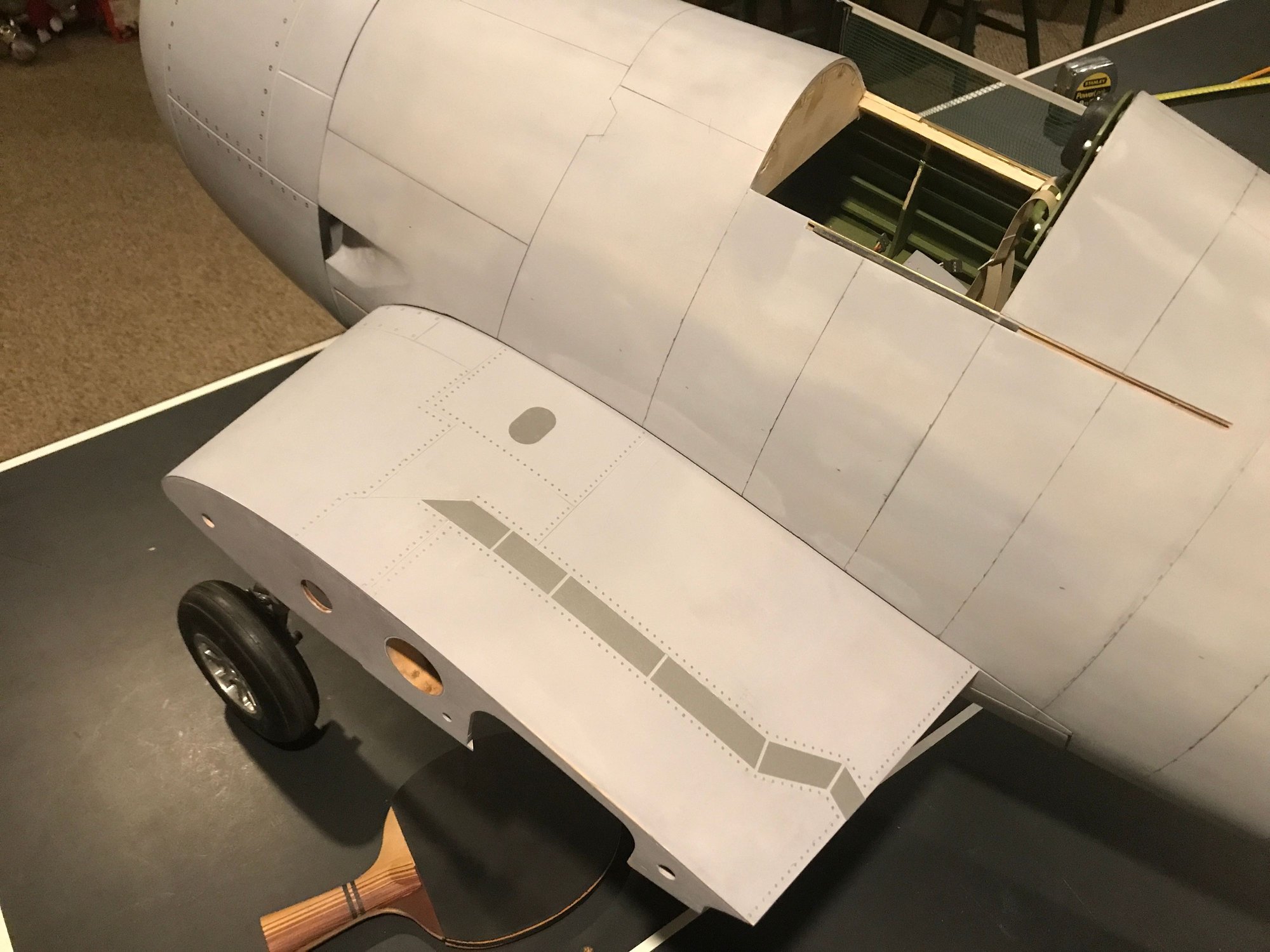
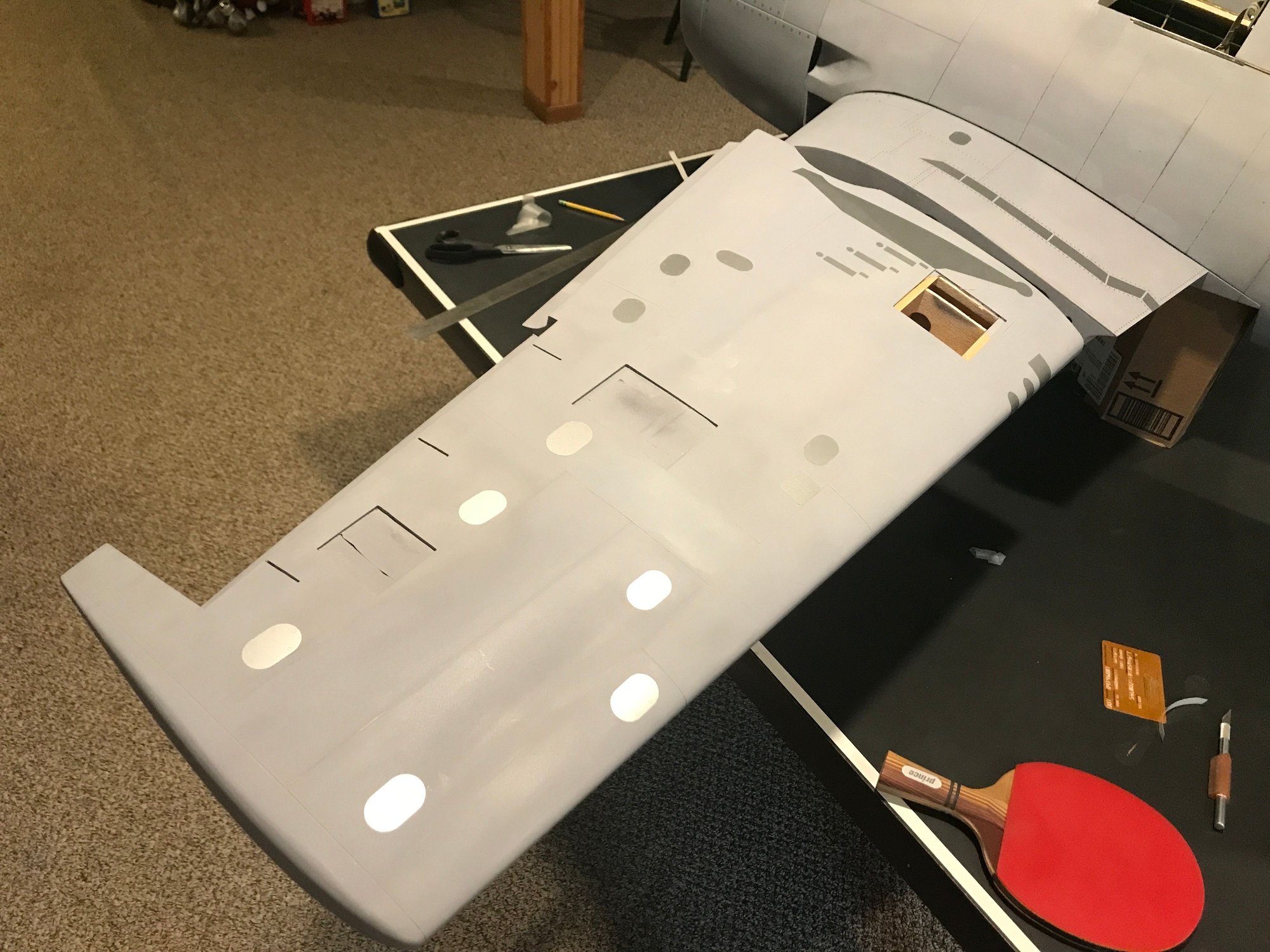
Detail panels, dummy rivets for left outer wing panel done - for now. A still need a couple good wing pictures, top and bottom from a real Hellcat to confirm that I've done enough or not. I also have some access hatches (aileron servo, dummy guns) where I need to decide if they are done as is or need any enhancement with some dummy screws/rivets. For now, calling it good enough and moving on to complete the right outer wing panel bottom.
About 3400 dummy rivets applied, so far.
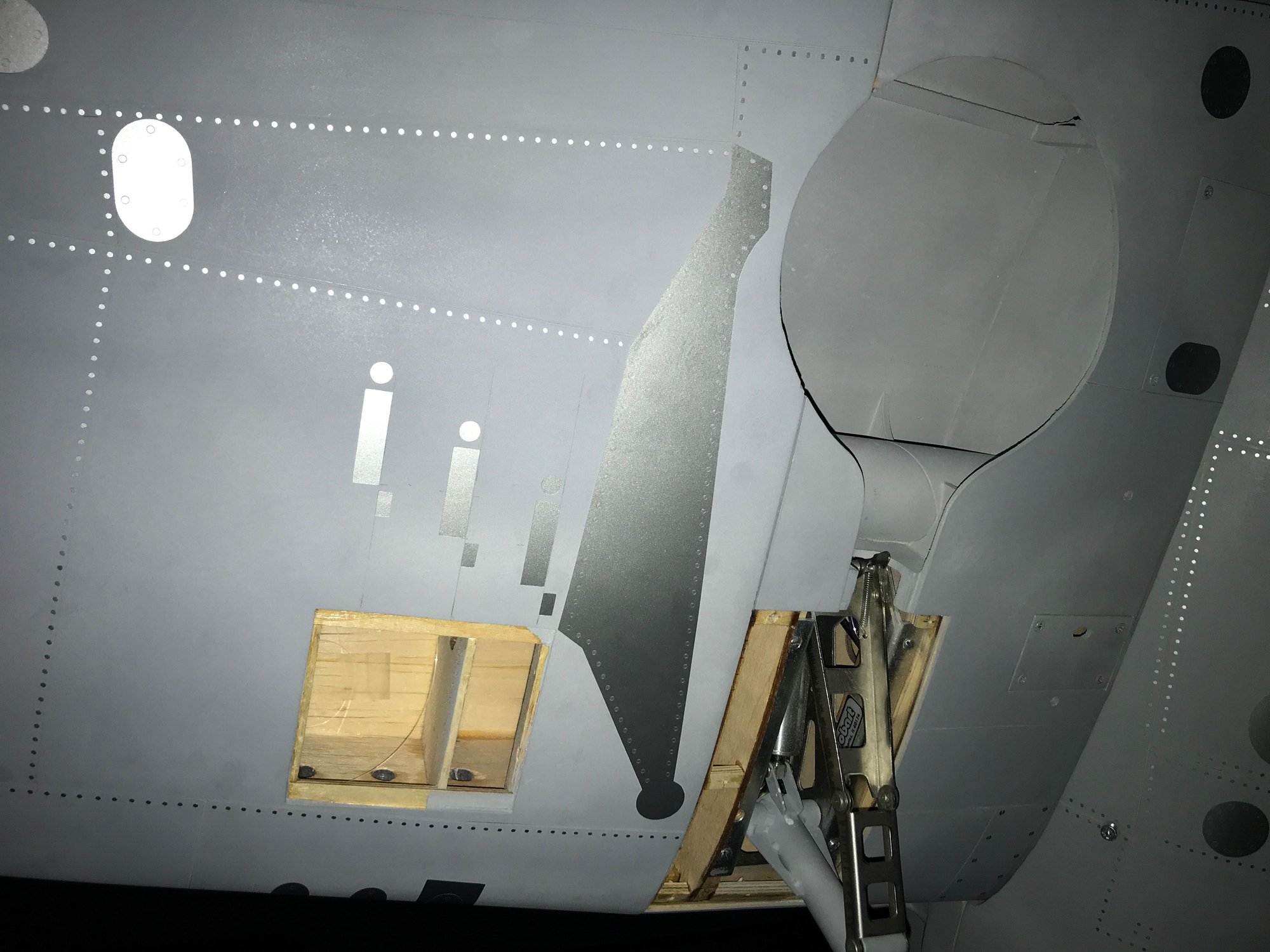
Note the long triangular panel to the right of the shell casing exhaust ports - rimmed with dummy rivets per the Eduard model.
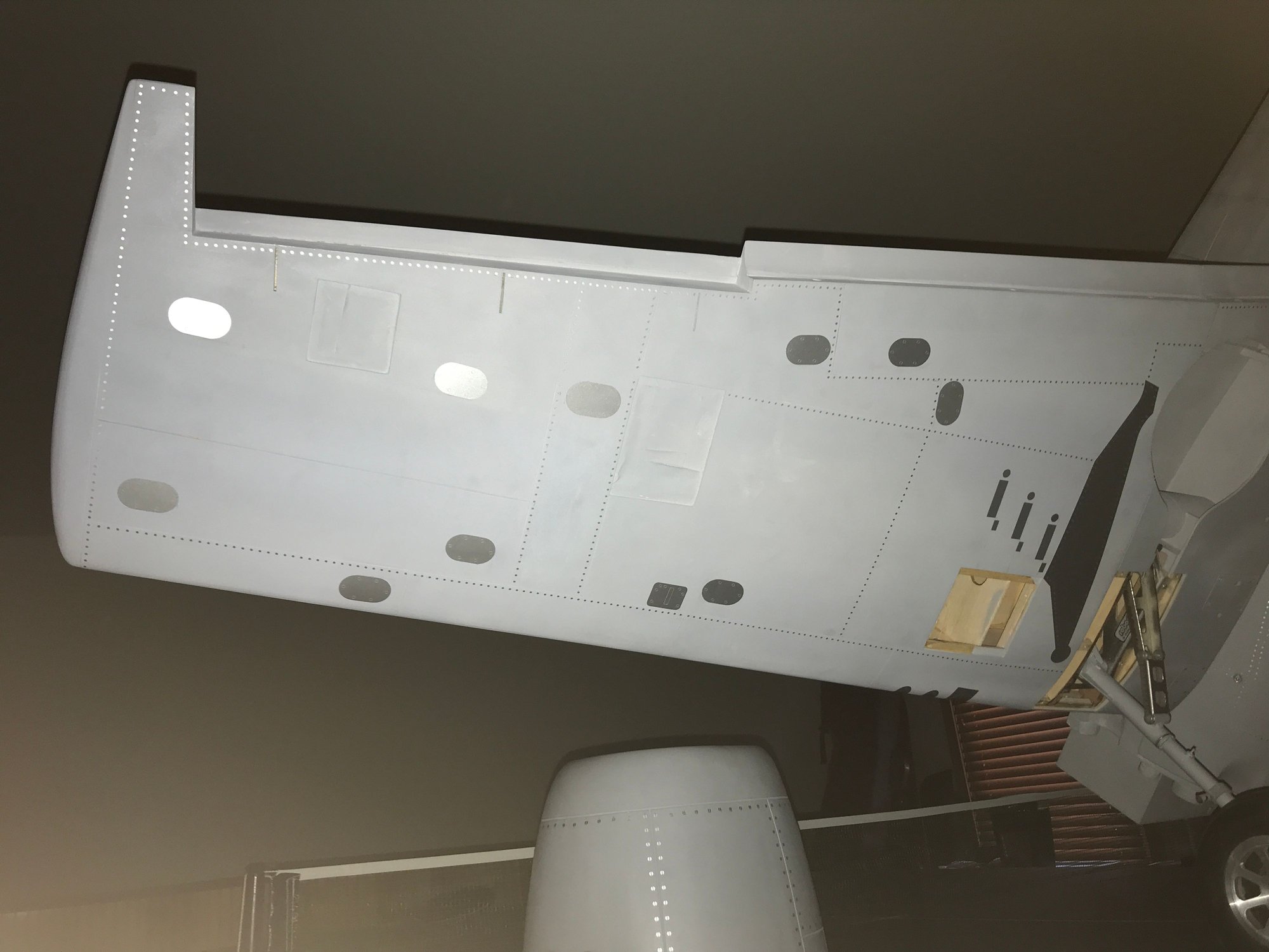
Left wing, complete - for now.
About 3400 dummy rivets applied, so far.
Note the long triangular panel to the right of the shell casing exhaust ports - rimmed with dummy rivets per the Eduard model.
Left wing, complete - for now.
03-11-2024, 05:47 PM
#347
Thread Starter
No progress over the last week as I was in Sun Valley, ID for 8 days. Didn't see any potato trees. Apparently they are a bit further south. Did see some elk and then a bald eagle flying about 20 feet above the Salmon River. Beautiful country.
Back, now, and the wing essential details are done. I may do more rivet details, but need to find some better wing pictures for confirmation. Also, I'd like to get started on masking and line taping the fuselage for creating the panel lines. Days are getting warm enough in SE Michigan to move the priming to the garage.
Back, now, and the wing essential details are done. I may do more rivet details, but need to find some better wing pictures for confirmation. Also, I'd like to get started on masking and line taping the fuselage for creating the panel lines. Days are getting warm enough in SE Michigan to move the priming to the garage.
 03-12-2024, 11:53 AM
#349

My Feedback: (60)
Join Date: Dec 2001
Location: Litchfield Park,
AZ
Posts: 7,677
Likes: 0
Received 25 Likes
on
23 Posts
The best Hellcat drawings out there can be found at the link below and include all of the rivet details you will ever need.
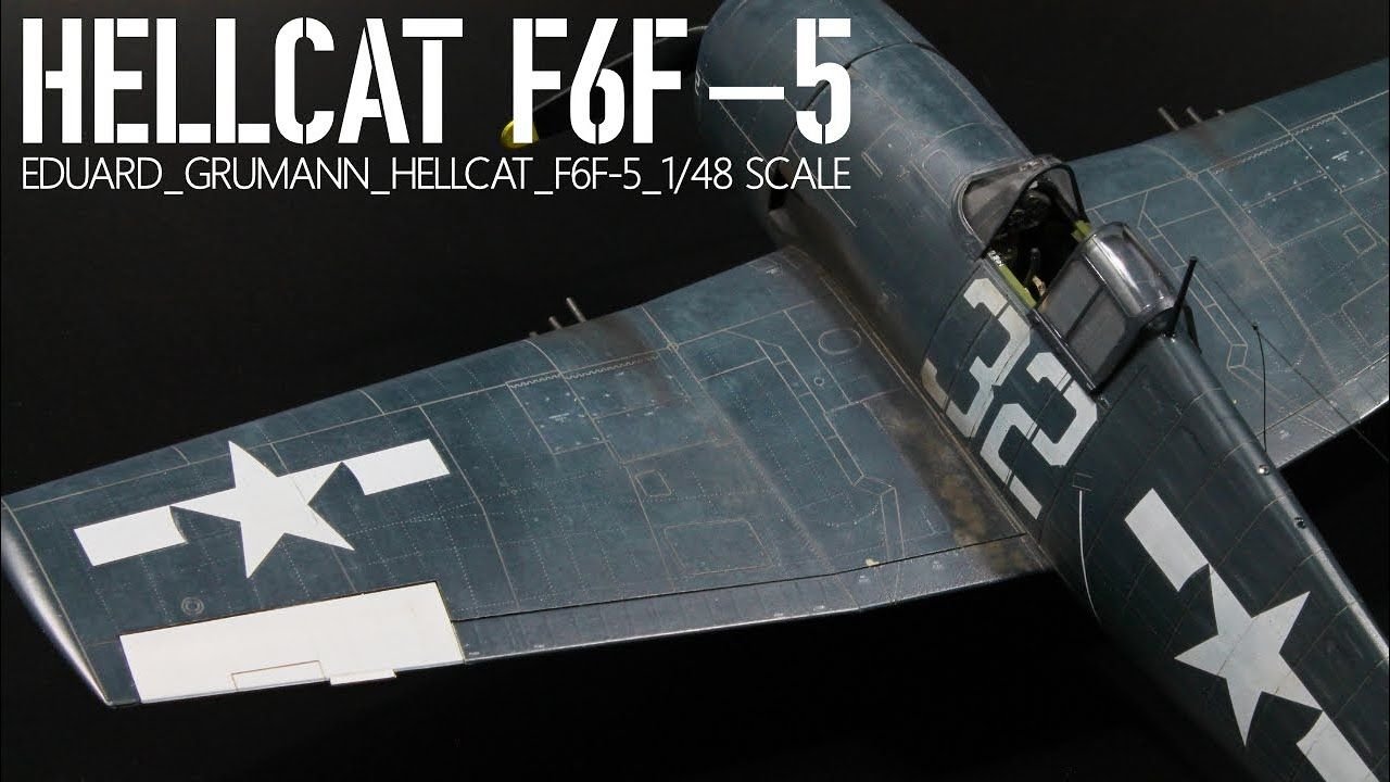
f6f hellcat part-1 Hasegawa 1/48
f6f hellcat part-1 Hasegawa 1/48
03-13-2024, 02:13 PM
#350
Thread Starter
The best Hellcat drawings out there can be found at the link below and include all of the rivet details you will ever need.
f6f hellcat part-1 Hasegawa 1/48
f6f hellcat part-1 Hasegawa 1/48