


CARF SPITFIRE ASSEMBLY and SCALE DETAILING
 04-26-2016, 03:56 AM
#1
Member
Thread Starter
Join Date: Aug 2013
Posts: 36
Likes: 0
Received 0 Likes
on
0 Posts
I just returned from the US visiting my son and brought back my new 1/4 scale Spitfire from CARF. Normally I would have waited until October to start the build, but because I will be having some extensive health treatments soon, I decided that starting the build now would help keep my mine well occupied and not let me dwell on the negatives.
There are several Carf Spitfire builds out there and I will post links to them for anyone wanting to also go down this trip. I will be adding some extra scale items to make it stand out from some of the other builds.
Here is what I envisioned for my Spitfire.
A great sound in the air, so I got a Kolm 77cc 4 stroke engine for it. Carf suggests a DA 50 plus 4 pounds of lead to achieve the proper balance. Many others have opted for the DA 85 engine. This engine is heavy but I won't need much lead if I am careful during the build.
There are lots of versions to pick from, but I wanted one with a 3 bladed prop. The best examples of this are the Mk. V versions. This ARF also has the standard wing tips, standard rudder tip shape, early version of the elevators and the normal cockpit canopy. This then also limits the versions that you can choose from if your goal is to have it look semi scale.
With the choice of the Mk. V version comes with the option of 3 different wing armament (machine guns and cannons) and I will probably go with the "B" wing shape.
The nose shape is also up in the air but I probably will opt for the Volkes nose as this will allow me to get good cooling into the engine and still keep it's scale look.
Here is the paint scheme I plan to use.
 04-26-2016, 04:04 AM
#2
Member
Thread Starter
Join Date: Aug 2013
Posts: 36
Likes: 0
Received 0 Likes
on
0 Posts
REFERENCE MATERIAL
Here is what I am using for guiding me through on some of the scale details that I will be using. The MORFORTON book is the ultimate for learning every dimension on the real Spitfire. Even though it is for the Mk. IX version, MOST of the dimensions apply to the earlier Spitfire builds. You can buy a PDF download of this 490 page document for$23.50 . A great purchase.
http://www.monfortonpress.com/
John Allan supplied me with the other books that I am using for reference. The variations of Spitfires even within one of the Mx. Version are numerous. This allows us to certainly have a unique plane from one another.
04-26-2016, 11:55 AM
#3
Member
Thread Starter
Join Date: Aug 2013
Posts: 36
Likes: 0
Received 0 Likes
on
0 Posts
FUSELAGE FIREWALL
The engine I picked was the Kolm 77cc 4 Stroke with the large prop shaft extension. I did that because the cylinder head is so tall, I needed to put it as far back into the slim cowl as possible.
This choice makes it so I don't have the head hanging out on the bottom and ruining the scale look.
For future reference to new builders the distance to the FRONT of the Cowl fro the forward edge of the firewall is 185mm. If you are using a different engine that number will guide you if you will have enough room with out removing the firewall.
With the Kolm engine, that meant I had to remove 43mm and add a new firewall. The trick to making an accurate cutting line is to put the fuse rudder up and on its firewall and scribe a line all the way around. I then added two layers of 1/4 inch flexible tape to help me guide the Dremel diamond wheel as I cut the nose off.
There is a lot of discussion in some of the other build threads about how much offset needs to be built in. NONE NONE NONE! This information is right from CARF.
I built the firewall from 1/2 inch Birch plywood. I laminated the edges and inside with WEST Epoxy (slow cure) and added WEST 2 inch wide carbon fiber strips to give it extra strength. On the outside I put Finishing Epoxy to completely fuel proof it.
Here are the weights before and after.
ORIGINAL FUSELAGE 1350 grams
ORIGINAL FIBERGLASSFIREWALL REMOVED 66 grams
ORIGINAL WOOD FIREWALL SUPPLIED BY CARF 106 grams (but no glue or reinforcing tape)
NEW FUSELAGE WITH NEW FIREWALL 1620 grams.
So I have added a total of 270 grams. It would have been 170 grams with the CARF Firewall system as it is somewhat thinner.
At least the weight addition is up front.
04-26-2016, 12:50 PM
#4
Member
Thread Starter
Join Date: Aug 2013
Posts: 36
Likes: 0
Received 0 Likes
on
0 Posts
PLASTIC MODEL REFERENCE KIT
I bought this Tamiya 1/48 plastic kit for reference.
The CARF is a 1/4 scale plane (actually 23%) so it's easy to upscale a unique part on the plastic kit by multiplying it by 12.
This kit has the very unique Tropical filter used in the Mediterranean action. With the inlet so far forward it should be easy to get lots of air to the fins of the engine by using good baffling.
Last edited by krazy kanuk; 04-27-2016 at 03:33 AM.
04-28-2016, 04:52 AM
#5
Member
Thread Starter
Join Date: Aug 2013
Posts: 36
Likes: 0
Received 0 Likes
on
0 Posts
COWL ATTACHMENT
On the real aircraft all around the fuselage and Cowl, they used DZUS Fasteners.
But this CARP Spitfire was built with Exposed Phillips Head Screws as can be seen in picture 1.
To hold the cowl on, I can't duplicate a true Dzus fastener system in a logical timely manner, so I am going to keep what's there.
I found a 4-40 machine screw that has the perfect head diameter and with the combination Roberson Slot head is the same size in diameter and height. I had to sand the small bump down with a diamond file to have the screw sit flush.
To attach the screws to the inside of the fuselage, I used Wood Mushroom Caps used in the furniture industry to hide screw heads. I drilled then tapped them to a 4-40 thread. To hold them in place I used HYSOL 9462 glue.
I used a total of 8 screws and Mushroom caps.
The total weight gain for this was part of the build was 12 grams (not counting the glue weight).
04-28-2016, 04:55 AM
#6
Member
Thread Starter
Join Date: Aug 2013
Posts: 36
Likes: 0
Received 0 Likes
on
0 Posts
For those interested in reading about "The Ultimate" in scale building of a Spitfire go to RC SCALE BUILDER and read Detlof Kunkel's notes on his 1/4 Spitfire MK VIII using Mike Reeves kit. He started the build in April 2010 and is still at it in April 2016.
It's a fascinating read!
http://www.rcscalebuilder.com/forum/...886&PN=1&TPN=1
It's a fascinating read!
http://www.rcscalebuilder.com/forum/...886&PN=1&TPN=1
 04-30-2016, 04:15 AM
#8

My Feedback: (1)

Join Date: Jul 2004
Location: Perth WA, AUSTRALIA
Posts: 2,200
Likes: 0
Received 0 Likes
on
0 Posts
Hi krazy kanuk,
This sounds like a wonderful project. I just wanted to let you know that if you are going for real scale then you will have to shorten the cowl if you want to do a Vokes filter as the MkIX (as in the CARF kit) had a longer cowl than the MkV that actually made use of the filter. If it is going to be sports scale it will be just fine and be an effective way of cooling that in line engine.
I'm subscribed either way.
Cheers,
Brad
05-02-2016, 03:37 AM
#9
Member
Thread Starter
Join Date: Aug 2013
Posts: 36
Likes: 0
Received 0 Likes
on
0 Posts
RUDDER DETAILS
My goal is to add simple scale effects to the Spitfire that will stand out when you first approach the plane.
On the Rudder I have added the Navigation Light and the Trim Tab control mechanism.
I found the "Perfect" Light Bulb 0.375" in diameter at Advance Auto.
For the Trim Tab components I purchased them from Nick Ziroil.
https://ziroligiantscaleplans.com/pl...cessories.html
The MONFORTON book gives every dimension that you would need to put the light and trim tab in the proper location.
The Rudder control on the spitfire does not use our traditional Pull-Pull system so I had to compromise a bit to make it look somewhat real and yet be quite sturdy enough.
I scored the hinge line for the trim tab and added a tiny thin wire to give it that more scale look. After sanding the components down I painted it uses a Etching Primer.
The original weight of the Rudder was 82 grams and it is now up to 112 grams. Unfortunately at the wrong place to be adding weight to a war bird, but I believe the engine is heavy enough to compensate for this tiny increase.
05-02-2016, 03:41 AM
#10
Member
Thread Starter
Join Date: Aug 2013
Posts: 36
Likes: 0
Received 0 Likes
on
0 Posts
Hi krazy kanuk,
This sounds like a wonderful project. I just wanted to let you know that if you are going for real scale then you will have to shorten the cowl if you want to do a Vokes filter as the MkIX (as in the CARF kit) had a longer cowl than the MkV that actually made use of the filter. If it is going to be sports scale it will be just fine and be an effective way of cooling that in line engine.
I'm subscribed either way.
Cheers,
Brad
This sounds like a wonderful project. I just wanted to let you know that if you are going for real scale then you will have to shorten the cowl if you want to do a Vokes filter as the MkIX (as in the CARF kit) had a longer cowl than the MkV that actually made use of the filter. If it is going to be sports scale it will be just fine and be an effective way of cooling that in line engine.
I'm subscribed either way.
Cheers,
Brad
As I just discovered that my illness has progressed much farther than anticipated I will have to limit my extra scale adding details.
05-02-2016, 04:33 AM
#11
Member
Thread Starter
Join Date: Aug 2013
Posts: 36
Likes: 0
Received 0 Likes
on
0 Posts
UPPER NAVIGATION LIGHT
This was my first try at Vacuum forming. John Allen lent me his box to make the dome light.
For those that are new to this it does take some experimentation, but the results are certainly worth it. I made a wooden plug "tried Balsa but like soft pine better). After putting on several coats of Urethane I then pulled a 0.015" styrene part. From reading others vacuum trials, this acts as an excellent base to pull the clear plastic over. It produces a super smooth finish. I tried making the clear plastic part from 0.015" plastic but it just was not rigid enough so I ended up using 0.030" material. This produces the perfect strength of part.
The light bulb comes from Advance Auto at the correct diameter of 0.375" for a 1/4 scale plane. The mounting plate is made from 0.030" styrene that is held in place with some #0 screws. The inside was painted with an etching primer that has the "Almost Right Look" for any interior metal parts on the real Spitfire.
When ready for painting the mounting plate will be the correct colour of the fuselage, just the interior where the bulb is will remain green.
The net gain in weight to the fuselage for this small scale feature was 18 grams.
Again the MONFORTON book gives all the dimensions for you to make your own Navigation Light.
And again don't loose sight of the overall game plan, this is a Sports Scale Plane and minute deviations are accepted as long as the "Message is There"!
05-02-2016, 04:06 PM
#12
Member
Thread Starter
Join Date: Aug 2013
Posts: 36
Likes: 0
Received 0 Likes
on
0 Posts
Taking a short break from the Spitfire build to head south to Joe Nall with Jim Bisson. We leave tomorrow at 7:00am.
Roger "Ramjet" came over tonight and helped get the Landing gear to sit flush on the wood mounts. Thanks Roger.
I will be back at it in 12 days!
Roger "Ramjet" came over tonight and helped get the Landing gear to sit flush on the wood mounts. Thanks Roger.
I will be back at it in 12 days!
05-15-2016, 04:21 AM
#13
Member
Thread Starter
Join Date: Aug 2013
Posts: 36
Likes: 0
Received 0 Likes
on
0 Posts
ELEVATOR CONTROL SYSTEM
Well I'm back from 11 great days at Joe Nall. There were four other Spitfires (3 from Germany) that I got to watch fly and take lots of pictures on how each one did some unique things to their planes.
The control of the elevator is done with a long carbon fiber shaft that has two ball links attached to it.
I personally like to use the SDS carbon fiber tray to hold the servo and use the auxiliary ball bearing pivot to reduce the stresses on the servo gear train.
These are available at SDS Hobbies SKU SACF20111 for $17.29.
I am using Savox Brushless 2270 servos on all of the flying servos. I have had great success on all of my other planes using them and they don't draw a lot of power during the flight. The torque for this servo is 444 oz. inches at 0.12 seconds.
I did learn that the elevator on this Spitfire design is very sensitive and you need a lot of Expo around 65%. On landing about 1mm of down is required when the flaps (really an airbrake) are deployed. Two of the German flyers (who are part of a massive 9 plane war bird flying event at the noontime show) both use some Butterfly in their aerilons during landing. There is no mention of this in the Carf Manual.
Here are the weights of the items added to the Spitfire.
Control Rod with 2 Ball Links 52 grams
Elevator CF tray with Control Horn 32 grams
Servo with Arm and 2 Ball links 80 grams
http://www.sdshobby.com/catalogsearc...SACF2011&cat=0
 05-15-2016, 11:16 AM
#15
Member
Thread Starter
Join Date: Aug 2013
Posts: 36
Likes: 0
Received 0 Likes
on
0 Posts
FUEL TANK
The Monforton book on page 2.31 lists the location and size of the fuel intake in the fuselage along with the two breather holes. I tried to simulate the size and shape with the existing fuel dots that are available. As this is a Sports Scale version, I'm not worried that the fuel dot is a 1/32 inch too big.
Thunderbolt RC sells a new Seacraft fuel bottle holder that worked very well for my situation. I was able to shape it to the fuselage shape and I held it in place with Hysol 9462 Epoxy. It will never move!
The mounts only weigh 32 grams. http://www.thunderboltrc.com/index.p...oducts_id=2155
I was able to put the fuel tank exactly over the CG for this airplane, so I should have no trouble with the trim as the fuel is used up. I'm using a 50cc tank for the 77cc 4 Stroke engine, but if I need more it is easy to add a Pepsi 710cc tank.
I personally like using the quick disconnects from Thunderbolt, it makes it very easy to remove the tank in seconds. The one on the line to the engine even has a quick shut off so if there is any tank it won't leak out. http://www.thunderboltrc.com/index.p...oducts_id=1300
05-15-2016, 11:19 AM
#16
Member
Thread Starter
Join Date: Aug 2013
Posts: 36
Likes: 0
Received 0 Likes
on
0 Posts
Do you mean the Carbon Fiber to hold the firewall in place? If so I bought it at my local hardware store that sells a lot of the West Epoxy Boat repair systems. It only comes in one size at this store (Home Hardware in Canada).
05-20-2016, 06:04 AM
#18
I'm so happy to see your are doing the livery scheme of Canada's top scoring Spitfire ace from WWII "Buzz Beurling"! It's very refreshing to see a Spitfire with lettering other than JEJ!
Roger
Roger
05-30-2016, 03:53 AM
#19
Member
Thread Starter
Join Date: Aug 2013
Posts: 36
Likes: 0
Received 0 Likes
on
0 Posts
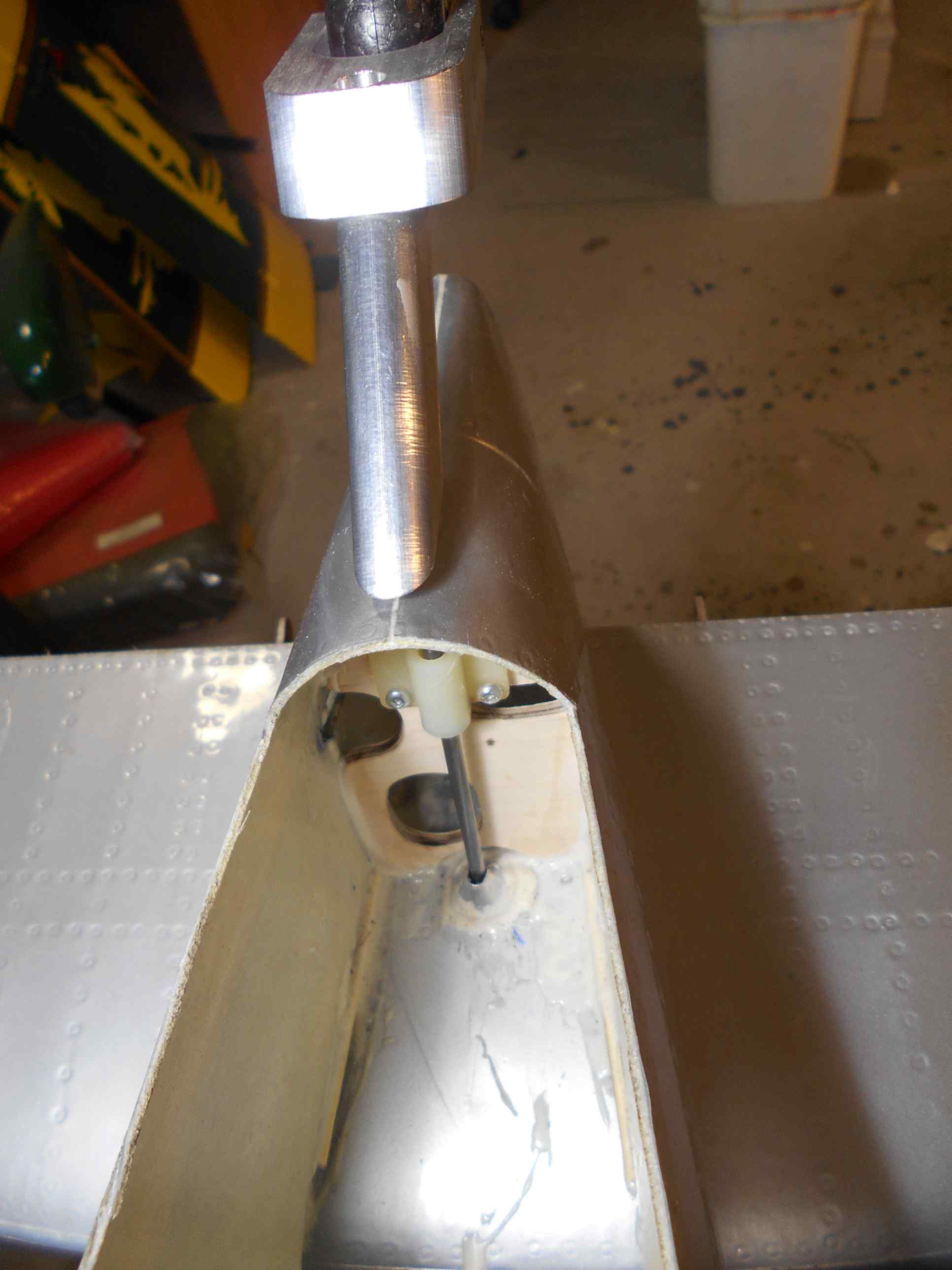
TAIL WHEEL BRACKET
I have had too many visits to three hospitals and I don't know how many doctors to let me work on this project. But finally I have been able to get back to it.
I decided to go with a Steerable Tail wheel and opted for one made by Shindin Machine http://www.shindinmachine.com/SPITFIRE/SPITFIRE.html.
This tail wheel uses the same steering technique as a trike nose wheel.
My first step was to install two aluminum bushing mounts to control the 5/32" steering rod. These were put in place with more Hysol EA 9462 Locktite glue.
Next, I made the vertical support plate out of 3/16' birch plywood. As you can see there are a lot of holes in it for the two pushrods and for the steering arm. Making this part takes a lot of time getting the correct profile shape. I first made a card stock template, followed by a balsa template and then a thin plywood template. Once that I was happy that I had the correct profile shape with the holes in the proper position and large enough, I made the final 3/16" birch former. I sanded the sides at a 6 degree taper so that it would fit snugly against the fuselage.
Total weight for just the former and its supporting hardware is 39 grams. This does not count the tail wheel and the control rod!
Next is to build the tail wheel servo box.
05-31-2016, 03:26 AM
#20
Member
Thread Starter
Join Date: Aug 2013
Posts: 36
Likes: 0
Received 0 Likes
on
0 Posts
TAIL WHEEL CONTROL SYSTEM
I opted to put in a Hitec 5087 metal gear micro servo to control the tail wheel. I will program (using a separate channel), this servo to my rudder and will then be able to have it work in the right amount for deflection when I use the rudder for steering.
http://hitecrcd.com/products/servos/...servo-/product.
The servo tray is made from items supplied by Carf for this kit. I plan to assemble the aerilons using a different holding technique, so this wooden tray was available. Again I used Hysol Locktite glue to hold it to the side of the fuselage. If I need a larger servo, the tray is easy to open up the space to slide in a bigger style of servo.
Weight for the tray was 18 grams and the servo was 22 grams.
Next to carefully attach the hatch back to the fuselage and the tail wheel project will be DONE!
06-01-2016, 11:13 AM
#22

Great job so far, thanks for sharing. I have the CARF mustang, corsair and had the P-47. Might not be a bad idea to reinforce the nose area a bit more. You will need the weight, and its good piece of mind to have the area stronger. I would run carbon or glass back to the front of the canopy. I took the nose off my P-47, not a fun rebuild.
Look forward to following.
Look forward to following.
06-03-2016, 06:55 AM
#23
Member
Thread Starter
Join Date: Aug 2013
Posts: 36
Likes: 0
Received 0 Likes
on
0 Posts
Great job so far, thanks for sharing. I have the CARF mustang, corsair and had the P-47. Might not be a bad idea to reinforce the nose area a bit more. You will need the weight, and its good piece of mind to have the area stronger. I would run carbon or glass back to the front of the canopy. I took the nose off my P-47, not a fun rebuild.
Look forward to following.
Look forward to following.
06-04-2016, 03:04 AM
#25
Member
Thread Starter
Join Date: Aug 2013
Posts: 36
Likes: 0
Received 0 Likes
on
0 Posts
Attaching the radio antennae to the fuselage left me with a challenge. I have seen too many war birds where the antennae has been broken off when the plane is turned upside down for assembly. I wanted to make mine EASILY removable for transportation.
I found some teardrop tubing used for struts that was just the right width. I also had an plastic insert for it that was shaped so the end would be able to pivot against the fuselage. I think this is old Byron material I had laying around.
I shaped the antennae per the dimensions in the MONFORTOM book. I added a second piece of the shaped tubing to the inside of the fuselage and place the two piece base around the tubing that is inside the fuselage. The plastic insert is glued to the antennae and the remainder of the insert is now able to be forced into the fuselage tubing.
It is a very difficult part to assemble or remove so I have NO worries that it will be lost during flight.

