


Skyshark Dauntless Build
 12-26-2015, 01:00 PM
#1

Thread Starter
Anyone who's looked at my past threads they know my admiration of the smaller .50 size kits that are out there or were out there through the years. I like to take those smaller kits and make them as close to the prototype while still maintaining fly-ability and my own sanity! LOL
I've searched on many sites and while I've found some on the SS Dauntless, most of those threads drop off before the maiden and never come back to life. I hope to continue this thread all the way til the maiden and give it a total review. Like my other build, it will be doing some modifications to make it more prototypical. The SS kit is high quality as most know with a really nice scale outline. While it offers scale like hinging of the flight surfaces, the retracts are an area that aren't even close. On the prototype, the struts are at a slight angle with the axle at a corresponding angle to put the wheel at 90d to the wing. To accomplish this with working oleo struts, a strut will have to be made up on the lathe and vertical miller. I am using simple Hobby King electric retract units and old Kraft/Haynes scale 3" wheels. Instead of mounting the retracts level or close to level with the lower wing skin, I've mounted the retract at the greatest angle I could that would allow the retract to fit into the wing without the retract body from contacting the upper wing skin. Of course, mounting the retract unit this way, removes a lot of the reinforced rib that the retract mounting plate mounts to. Additional sheer web type reinforcing, with light ply, of the retract box will be added. Started the typical areas of the tail and also assembled the center section to the point of retract modifications.
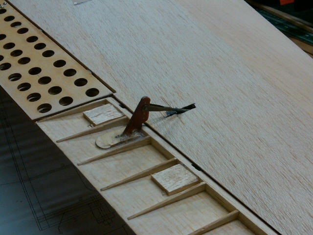
The SS kit uses the same sheeting and leading edge technique that the Top Flite kits do with the sheeting butting up to the back of the leading edge. I personally do not prefer this method as it's not as strong as laying the sheeting over the leading edge. I take the leading edge material and cut the matching angles of the upper and lower ribs on my dremel table saw so that I can lay my preglued sheeting right over the ribs and over the leading edge. Then the sheeting and leading edge are rounded together. My Tettra kits from Japan are designed this way and I will be doing this type of change to any kit I have that's done with the "butt" technique.
The SS kit also uses a unique system for the drive brakes that's tied into the flap servo linkage. This system only allows 1/2 flap because full flap deploys the dive brakes also. I am thinking of using torque rods for the dive brakes with a separate servo located centrally behind the aileron servo. I have the room in the center section because I will not be using air retracts. I will most likely stay with the nyrod type aileron linkage vs dual servos as this type of plane doesn't require anything more than that. I am thinking of putting the aileron horn on the top of the aileron edge which is prototypical but not sure as of yet. Rudder and elevator linkage will also be internal vs the plan's external configuration. Sig elevator horn is a great item I used in this build.
Power will be one of my .72 or .82 Saitos and will most likely have a bomb drop. Finish will be glass and paint with painted graphic, no decals. Going with an ordinary type color scheme on this one with weathering. Will probably be building a pair of .30 cals and gun ring for the back too.
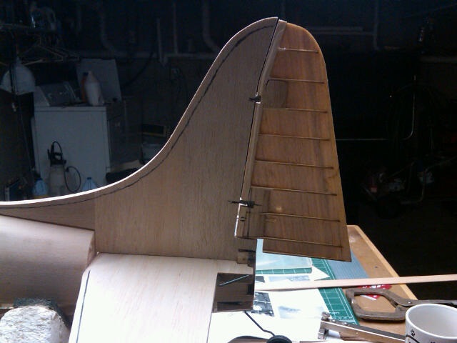
Well, that's the layout for this build so lets get it started. Here's some early shots of the fin with scale line hinging and the elevator with Sig elevator horn for internal linkage. Robart pin hinges will be used on most the hinged surfaces.
I've searched on many sites and while I've found some on the SS Dauntless, most of those threads drop off before the maiden and never come back to life. I hope to continue this thread all the way til the maiden and give it a total review. Like my other build, it will be doing some modifications to make it more prototypical. The SS kit is high quality as most know with a really nice scale outline. While it offers scale like hinging of the flight surfaces, the retracts are an area that aren't even close. On the prototype, the struts are at a slight angle with the axle at a corresponding angle to put the wheel at 90d to the wing. To accomplish this with working oleo struts, a strut will have to be made up on the lathe and vertical miller. I am using simple Hobby King electric retract units and old Kraft/Haynes scale 3" wheels. Instead of mounting the retracts level or close to level with the lower wing skin, I've mounted the retract at the greatest angle I could that would allow the retract to fit into the wing without the retract body from contacting the upper wing skin. Of course, mounting the retract unit this way, removes a lot of the reinforced rib that the retract mounting plate mounts to. Additional sheer web type reinforcing, with light ply, of the retract box will be added. Started the typical areas of the tail and also assembled the center section to the point of retract modifications.
The SS kit uses the same sheeting and leading edge technique that the Top Flite kits do with the sheeting butting up to the back of the leading edge. I personally do not prefer this method as it's not as strong as laying the sheeting over the leading edge. I take the leading edge material and cut the matching angles of the upper and lower ribs on my dremel table saw so that I can lay my preglued sheeting right over the ribs and over the leading edge. Then the sheeting and leading edge are rounded together. My Tettra kits from Japan are designed this way and I will be doing this type of change to any kit I have that's done with the "butt" technique.
The SS kit also uses a unique system for the drive brakes that's tied into the flap servo linkage. This system only allows 1/2 flap because full flap deploys the dive brakes also. I am thinking of using torque rods for the dive brakes with a separate servo located centrally behind the aileron servo. I have the room in the center section because I will not be using air retracts. I will most likely stay with the nyrod type aileron linkage vs dual servos as this type of plane doesn't require anything more than that. I am thinking of putting the aileron horn on the top of the aileron edge which is prototypical but not sure as of yet. Rudder and elevator linkage will also be internal vs the plan's external configuration. Sig elevator horn is a great item I used in this build.
Power will be one of my .72 or .82 Saitos and will most likely have a bomb drop. Finish will be glass and paint with painted graphic, no decals. Going with an ordinary type color scheme on this one with weathering. Will probably be building a pair of .30 cals and gun ring for the back too.
Well, that's the layout for this build so lets get it started. Here's some early shots of the fin with scale line hinging and the elevator with Sig elevator horn for internal linkage. Robart pin hinges will be used on most the hinged surfaces.

 12-28-2015, 09:47 AM
#3
Thread Starter
Good to hear about the flight characteristics. With those 1/8" ply flaps and dive brakes one can only imagine the weight has to be up there. My finishing techniques really help keep the finish weight down so I'll just have to see where it ends up. By using the electric retracts I'm saving weight and room there. Hopefully with the Saito, I'll have less useless weight to add for balance also. I try and use things like 6v packs, HiTed 225's, Saitos with custom exhaust, etc. to make better use of the essentials so total weight stays down. It's kind of a challenge I enjoy. I've built other planes that others have come out 1-3lbs heavier than mine for virtually the same air frame. A lot is careful planning and deviating off the plans more often than not. Today's engines, servos, materials can really help with this. The old Jemcos are another kit that can be lightened up a lot building them today VS when they were first offered. I'm seeing where some are up in the 9lb bracket with this plane and I feel I can be substantially below that but only the final of the build will see.
Last edited by chistech; 12-28-2015 at 07:14 PM.
 12-30-2015, 09:03 AM
#5
Thread Starter
Hi Tom,
Sent you a PM. It's good to be back but will be working on my new home business at the same time so the RC building will take a little longer than it used to. I will be building the skyraider in my usual style and trying to perfect painting/glassing techniques as I go. Also working on my Aero Tech Sea Fury too so I'll be doing two kits at the same time. Gerry is back to work on his Royal/Zero Rufe and I should be posting pictures and his commentary as I go.
Sent you a PM. It's good to be back but will be working on my new home business at the same time so the RC building will take a little longer than it used to. I will be building the skyraider in my usual style and trying to perfect painting/glassing techniques as I go. Also working on my Aero Tech Sea Fury too so I'll be doing two kits at the same time. Gerry is back to work on his Royal/Zero Rufe and I should be posting pictures and his commentary as I go.
01-03-2016, 07:24 PM
#6
Thread Starter
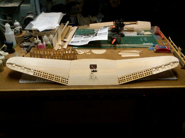
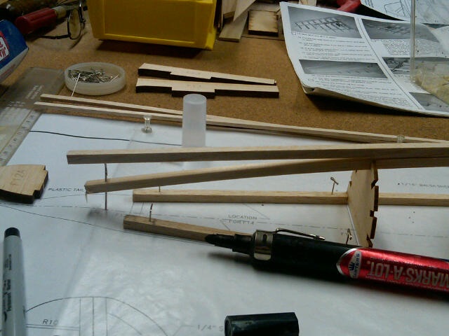
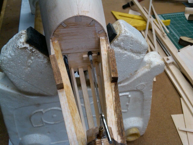
Got back from FL yesterday and did some more work on the Dauntless today. Had the retract units with the Kraft wheels on mounted in the frame and forgot to take a pictures. I made up the wheel well rings and sanded them down level with the top ribs. Can't get a picture now with the wheel well rings in place. Don't want to cut the rings at all until they're glued to the top sheeting. I epoxied in my retract mounts and made up some hardwood supports to strengthen the whole area. Took a picture of the HK retracts with the struts I'm using. Need to pickup some carpenter's glue to glue together my 1/16 sheets for the sheeting. Need some gorilla glue for my Aerotech Sea Fury kit too.
01-07-2016, 06:51 PM
#7
Thread Starter
Got a chance to work on the center section some more. Glued up and sanded my sheeting then sheeted the top. I decided to go with torque rods and a separate servo to control the dive brakes rather than use the single flap servo with special linkage. Set the retracts in and tested them for operation and angle. All looks good and they tuck in pretty good when retracted. Will need to make a servo mount behind the aileron servo to put the dive brake servo. Tomorrow with start putting the flap hinge supports and nyrods for the ailerons. I'm going with the old school single servo set up as it will be fine for this bird.
01-11-2016, 08:43 AM
#8
Thread Starter
Finished setting up the dive brakes linkage and servo in the wing top center section. Sheeted the bottom of the wing and cut out the retract/wheel well openings. Installed the recommended Y-harness for the flap servos and also the flap hinge blocks. Framed up the right wing and got it ready for sheeting.
One thing that's not mentioned in the instructions is the need for having your radio and receiver set up so you can properly align the bell cranks and flexible pushrod lengths. While most experienced builders understand this or use the small servo test boxes to do the set up, some might not and can end up with improperly set up bell cranks.
As I explained earlier, I prefer tapering the leading/trailing edge wood before I glue it to the framework and running the sheeting over the leading edge rather than doing it the kit designed way of butting the sheeting behind the leading/trailing edges. It is somewhat time consuming setting up a taper gauge to make these cuts but boy does it save a lot of time/mess planing/sanding of those edges.
01-11-2016, 11:49 AM
#9
Thread Starter
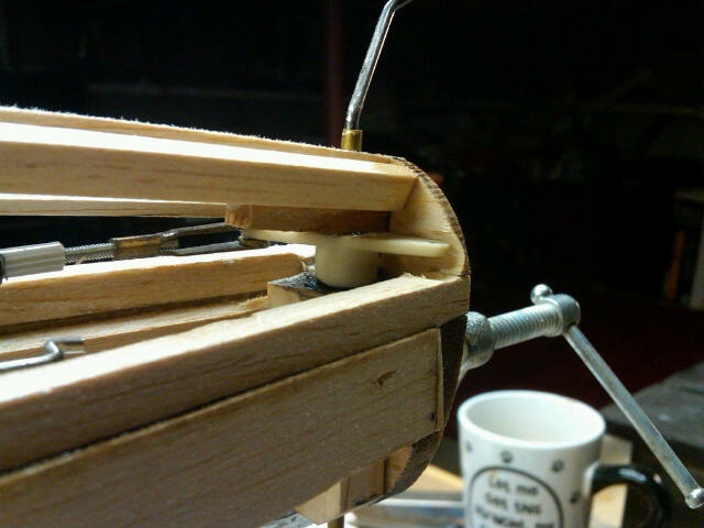
Dive Brake Hinging: I'm using robart 1/8 points and glued in my balsa support on the trailing edge. I used full width stock so I can put both the dive brake and flap hinges in the same block. I drilled the holes at a downward angle for more "meat" in the block with my intention of getting the hinge just under the height of the sheeting once it's applied. Using the Dremel table saw I held the 1/8 ply dive brake at a slight angle and cut slots for the hinge pin to lay in. This slot is just deep enough to again allow the hinge to be just under the height of the dive brake's upper surface. I sanded the back inside trailing edge of dive brake down to 1/32 to allow for a nice tight and thin match with the flap. I also sanded a 65d angle on the front of the dive brake so it can open up against the trailing edge of the top sheeting while still allowing virtually no gap while closed. Will start sheeting the top of the panel next. This kit builds the right outboard panel then the left. Happy with the outcome so far.
01-11-2016, 06:48 PM
#10
Thread Starter
While I glued up my sheeting and had it drying I worked on the aileron. I'm not a big fan of the beveled leading edge for ailerons so I doubled the aileron trailing edge between the ribs with the 1/4 balsa and I added a piece of balsa to the leading edge of the aileron. I then rounded the aileron leading edge completely and then sanding a corresponding half round into the trailing edge. I drilled both pieces for the Robart pin hinges and then put slots with the dremel so the hinges pivot point can be where it needs to be on the aileron. I made up my own ply control horn and cut into the aileron leading edge at the proper angle again with my dremel table saw. Will finish sanding the whole aileron down once all the sheeting in on and I have the proper shape to sand to.
01-12-2016, 10:46 PM
#12
Thread Starter
Had some trouble logging on tonight but finally got through. Got the top sheeting on the outer right panel. With a friend bringing up the concern of the ply control horn wearing out, I changed them out for reinforced fiber board/circuit board. Got the flap installed with it's hinges and also put in the flap in the center section. If the builder takes their time, very nice joints and gaps are easily made with this kit. The flaps, dive brakes, and ailerons really fit all nicely together.
This bird really looks good with the dive brakes and flaps open. In other build threads for this Skyshark kit, I've noticed many decide not to build in the dive brakes I think because of the complexity of the linkage used to operate them in the Skyshark manual. I'm glad I went the torque rod route and put the brakes in. Now, I couldn't see building it any other way. I have to say this is a pretty impressive kit that builds real nice. Because of all the moving parts it does take some time and some planning but I believe it will be worth it.
This bird really looks good with the dive brakes and flaps open. In other build threads for this Skyshark kit, I've noticed many decide not to build in the dive brakes I think because of the complexity of the linkage used to operate them in the Skyshark manual. I'm glad I went the torque rod route and put the brakes in. Now, I couldn't see building it any other way. I have to say this is a pretty impressive kit that builds real nice. Because of all the moving parts it does take some time and some planning but I believe it will be worth it.
01-13-2016, 07:53 PM
#13
Thread Starter
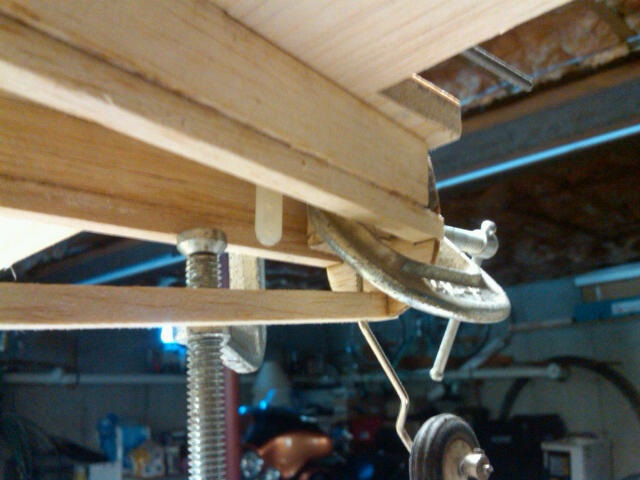
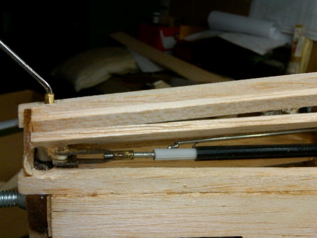
Set up the right flap servo linkage. I used a small CG control horn cut down some on the inside of the flap and put the control rod through the rear trailing edge. Using the small horn I needed less throw and a small servo arm. Because of the need for the flaps to close with some tension I set the control rod to allow the servo arm to be almost 180d (in the closed position) from the flap, lowering the tension on the servo drive gears and putting the tension more on the servo body. Setting it up this way allows the extra tension (tension is needed to fully close the ply flaps because of the slight warp they have and no hum from the servo).
Made up the support framework for the servo access door and sheeted the bottom of the wing. Sheeted the wing bottom and cutout the servo access opening. Because of the way the two flap servos are mounted in the wing, (because of the opposite rotation) one control rod needs towards the top of the rib, the other towards the bottom. Using the small servo arm allows all this to stay inside the wing with no issue.
When using the torque rods for the dive brakes, there is some movement of the brake end of the torque rod as the dive brake opens because of the dihedral. I made a small box to capture the end while still allowing the movement. Now the dive brake and the right side flap connections are all finished. I still need to make the connections on each side of the center flap to the respective outside flaps. I believe I will need the same sort of small box to allow for the control rod movement at these connections also.
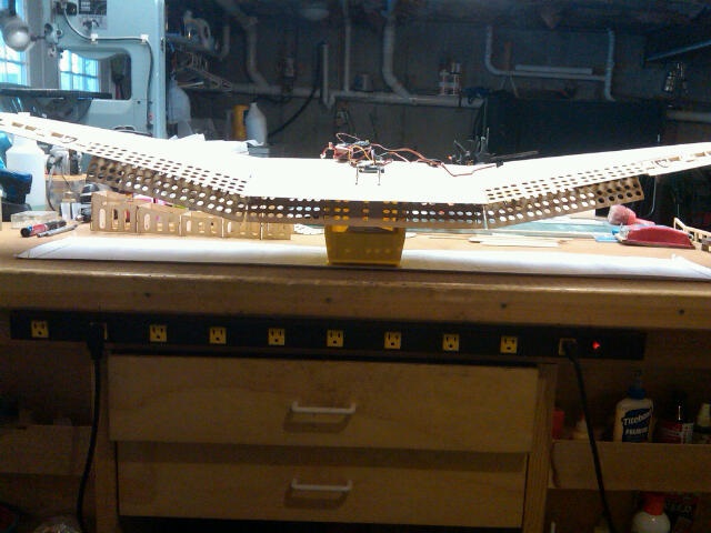
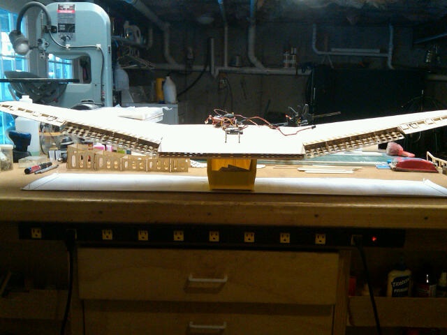
Set up some values in my trans for mixing Aux 2 to flaps. Now when Aux 2 (dive brakes) is actuated, both the dive brakes and flaps open/close. Attached a couple pictures of half dive brake and full brake positions all with connections made to servos. Seems to be working well.
Made up the support framework for the servo access door and sheeted the bottom of the wing. Sheeted the wing bottom and cutout the servo access opening. Because of the way the two flap servos are mounted in the wing, (because of the opposite rotation) one control rod needs towards the top of the rib, the other towards the bottom. Using the small servo arm allows all this to stay inside the wing with no issue.
When using the torque rods for the dive brakes, there is some movement of the brake end of the torque rod as the dive brake opens because of the dihedral. I made a small box to capture the end while still allowing the movement. Now the dive brake and the right side flap connections are all finished. I still need to make the connections on each side of the center flap to the respective outside flaps. I believe I will need the same sort of small box to allow for the control rod movement at these connections also.
Set up some values in my trans for mixing Aux 2 to flaps. Now when Aux 2 (dive brakes) is actuated, both the dive brakes and flaps open/close. Attached a couple pictures of half dive brake and full brake positions all with connections made to servos. Seems to be working well.
01-14-2016, 09:08 PM
#14
Thread Starter
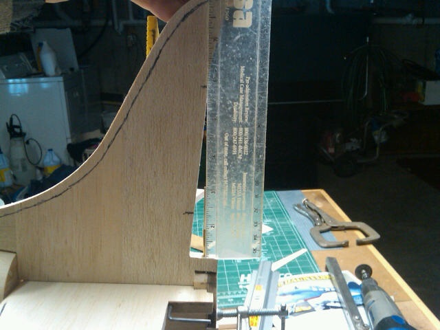
Didn't get much done today, didn't have a lot of time. Did get the wing tip shaped up and finished then framed up the left wing panel. I don't do the majority of the wing tip shaping with the tip glued to the wing. I instead trace the airfoil shape on the tip block then using the bandsaw, cut the tip to the first shape. I then use the razor plane to continue to shape it as close to what I need before I glue it on. Once glued, some blue painter's tape on the wing sheeting to keep the sanding bar off the sheeting while I sand the tip level with the sheeting. Doing it this way allow me to get the tip to shape much faster than trying to do it all while it's glued on. Starting to look like a Dauntless wing.
01-19-2016, 08:55 AM
#15
Thread Starter
[HR][/HR] Here is some pics of the wing all done. All linkages are hooked up but no hinges glued in yet and gear is in place. I realize that the gear legs on this and many dauntless models don't line up in the proper location on the wing dihedral joint but I'm OK with that. I more concerned with getting the proper strut look out of it. I don't like a lot of the new wave of Seagull and VQ Dauntlesses with the gear struts on the outside. Nothing wrong with the ARF's, just the retract strut layout.
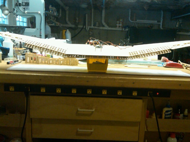
Half flap with flap switch
Full flap with flap switch
Half dive brakes/flaps deployed with Aux 2 switch (aux 2 switch mixed with flaps)
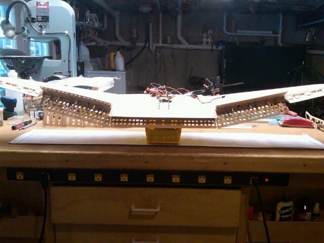
Full dive brakes/flaps with Aux 2 switch
Gear down
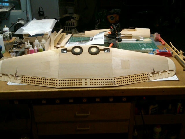
Wing bottom (something about a nice scale wing!)
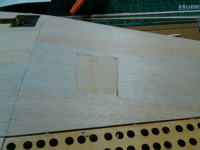
Servo access 1/16 ply covers
Mica control horn.
Half flap with flap switch
Full flap with flap switch
Half dive brakes/flaps deployed with Aux 2 switch (aux 2 switch mixed with flaps)
Full dive brakes/flaps with Aux 2 switch
Gear down
Wing bottom (something about a nice scale wing!)
Servo access 1/16 ply covers
Mica control horn.
01-19-2016, 08:56 AM
#16
Thread Starter
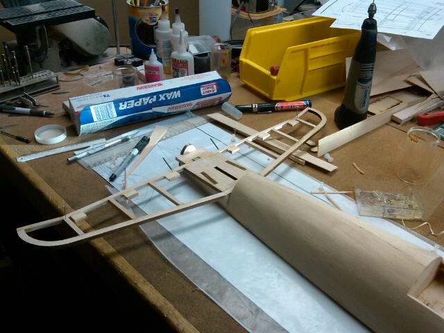
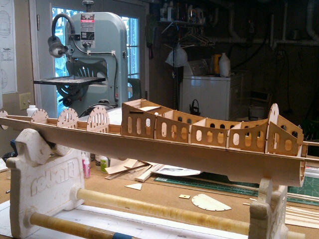
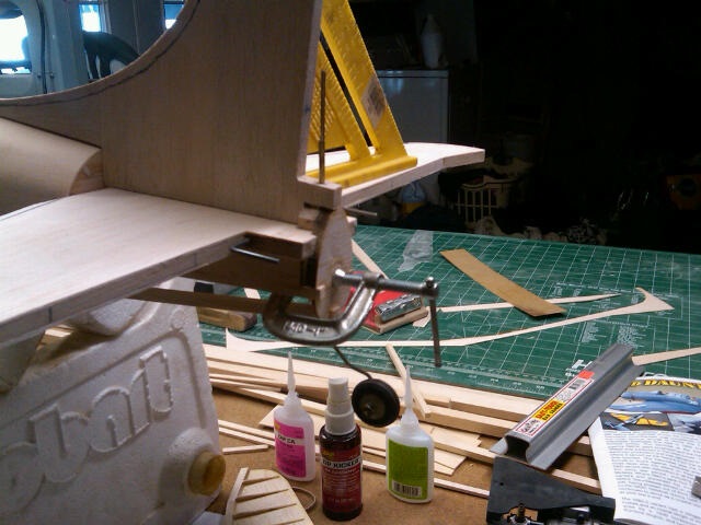
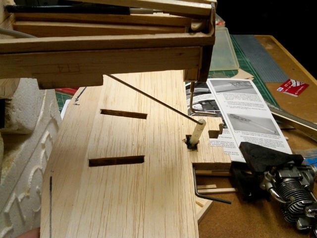
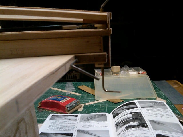
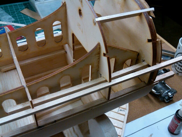
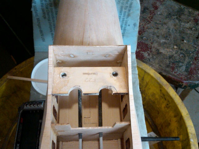
[HR][/HR] Got some work done on the fuse with the top section all finished. I got Brian's drawings and followed his suggestions for doubling up the stringers in the front. I cut all the grooves deeper before I started assembly. With the fuse formers so flimsy, I kept the 1/4 x 1/4 long and once the #8 former was square, I glued the 1/4 to it and pinned it to my board at the back. This allowed me to keep it square as I squared up the next one and glued it in place. Once the back was done, I took another full length 1/4 and lined up my forward formers while I had the 1/4 pinned to the rear 1/4sq. Picture will explain. All the rest of the fuse procedures was per the instructions. I used the 1/8 ply cut out pieces from the wing spar as the spacers for the sheeting at the 1/4sq fuse side spar.
NOTE: I am using a Saito .72 and to get the proper location for the motor thrust washer, the firewall was moved back 1/8" or just the width of the F13 firewall and F2/F2A
1/4sq left long and pinned down to the board to keep all the formers square
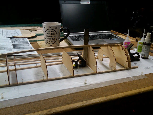
Squaring up the front formers with the 1/4sq left long and pinned to the rear one.
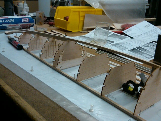
Another view
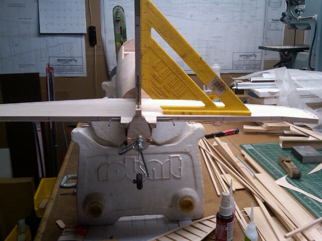
Put the stab on to align the f15 stab supports. Pins in out stab location for measuring
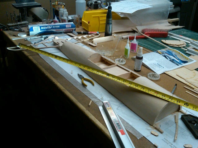
Measuring from corners to a pin set in center of 1/4sq in fuse top. All is good, glued in F15's
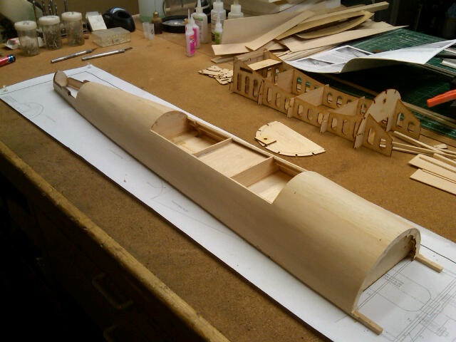
Fuse top finished for now
NOTE: I am using a Saito .72 and to get the proper location for the motor thrust washer, the firewall was moved back 1/8" or just the width of the F13 firewall and F2/F2A
1/4sq left long and pinned down to the board to keep all the formers square
Squaring up the front formers with the 1/4sq left long and pinned to the rear one.
Another view
Put the stab on to align the f15 stab supports. Pins in out stab location for measuring
Measuring from corners to a pin set in center of 1/4sq in fuse top. All is good, glued in F15's
Fuse top finished for now
01-19-2016, 08:57 AM
#17
Thread Starter
[HR][/HR] Did a quick alignment of the ply wing saddle pieces and the formers. Cut out clearance for the flap linkage. Epoxied the F2A ply piece to the F13 ply firewall. Will epoxy the firewall in when it's dry. Instructions have you do it in reverse. I thought it would be easier to put it in as an assembly.
NOTE: I had moved my firewall back 1/8" and had to cut 1/8" off the leading edge of the ply wing saddles. Also, because of the thrust built into the firewall, one side needs about 1/16" more off than the other to keep all straight. Use the other fuse formers installed in the fuse top to square it all off.
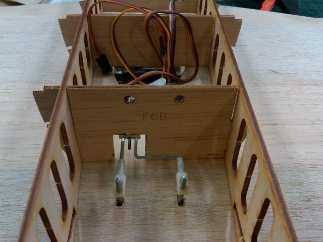
Clearance cut in F6B for the flap linkage
Just a mock up (not glued) of all the lower structure. Waiting for the fire wall to dry so I can install it.
NOTE: I had moved my firewall back 1/8" and had to cut 1/8" off the leading edge of the ply wing saddles. Also, because of the thrust built into the firewall, one side needs about 1/16" more off than the other to keep all straight. Use the other fuse formers installed in the fuse top to square it all off.
Clearance cut in F6B for the flap linkage
Just a mock up (not glued) of all the lower structure. Waiting for the fire wall to dry so I can install it.
Last edited by chistech; 01-22-2016 at 08:03 PM.
01-21-2016, 07:46 PM
#18
Thread Starter
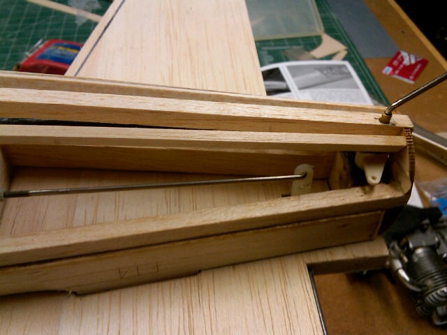
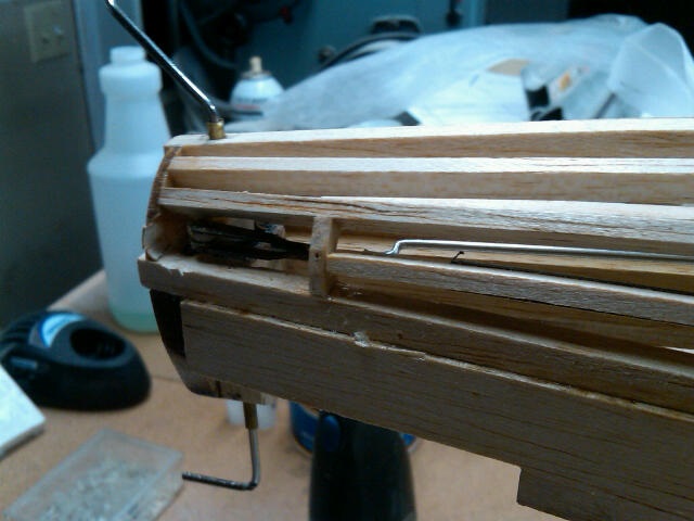
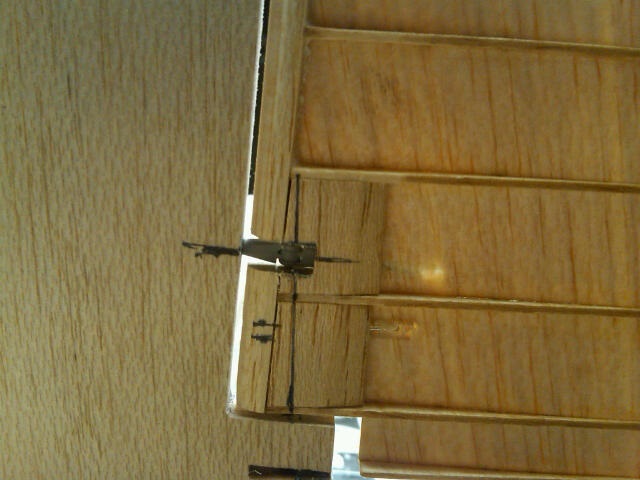
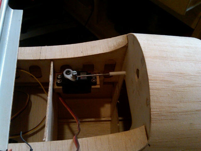
[HR][/HR] Sheeted the stab and fin then started setting up the tail wheel linkage before I move any farther on the strips and planking of the fuse. I'm running the rudder like the elevator so all will be internal. I used a small tail wheel control horn I had and it was perfect for this application. Ran a piece of brass tubing inside the tail wheel wire block to make it a better bearing.
This kit builds with a fair amount of distance with the bottom of the TW wire unsupported outside and below the block. At the bottom of the block is where my control horn is mounted then I glued another small piece of hardwood along the bottom 1/4 stringer with another piece of brass tubing for a lower bearing support. With the block in place, there is a fair amount of fitting and cutting of the rear of the stab to get the stab to sit down on the saddle. The TW wheel wire also comes up through the bottom of the fin bottom post so it's all got to be set up so it will work and also so it can be assembled.
I offset the elevator horn somewhat which allowed me to have clearance for both pushrods to work (elevator/rudder) I used a long length of wire at the end of the elevator pushrod and a Z bend to connect it to the elevator horn.
The stab in place with the elevator horn showing. Checking all clearances.
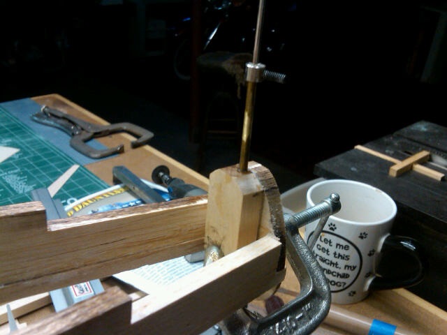
Tail wheel wire block in place with brass tubing. Need to cut the tubing to proper length yet.
Stab and rudder in place to check length of brass tubing and making sure everything fits right.
Rear view to check alignment.
checking hinge alignment with TW wire. It all lines up per plans.
Here's the off side view of the rudder control horn. I relieved the rear bulkhead for better rudder swing.
Pushrod and clevis attached to the horn.
This kit builds with a fair amount of distance with the bottom of the TW wire unsupported outside and below the block. At the bottom of the block is where my control horn is mounted then I glued another small piece of hardwood along the bottom 1/4 stringer with another piece of brass tubing for a lower bearing support. With the block in place, there is a fair amount of fitting and cutting of the rear of the stab to get the stab to sit down on the saddle. The TW wheel wire also comes up through the bottom of the fin bottom post so it's all got to be set up so it will work and also so it can be assembled.
I offset the elevator horn somewhat which allowed me to have clearance for both pushrods to work (elevator/rudder) I used a long length of wire at the end of the elevator pushrod and a Z bend to connect it to the elevator horn.
The stab in place with the elevator horn showing. Checking all clearances.
Tail wheel wire block in place with brass tubing. Need to cut the tubing to proper length yet.
Stab and rudder in place to check length of brass tubing and making sure everything fits right.
Rear view to check alignment.
checking hinge alignment with TW wire. It all lines up per plans.
Here's the off side view of the rudder control horn. I relieved the rear bulkhead for better rudder swing.
Pushrod and clevis attached to the horn.
01-21-2016, 07:49 PM
#19
Thread Starter
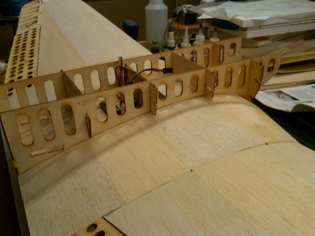
[HR][/HR] Will all the tail appendages in clamped and place and all linkages installed I started to finish up the adding the strip wood to the formers.
Here is the elevator pushrod going in as the stab is trial fit with linkage hooked up.
Stab in place with elevator linkage and rudder horn visible.
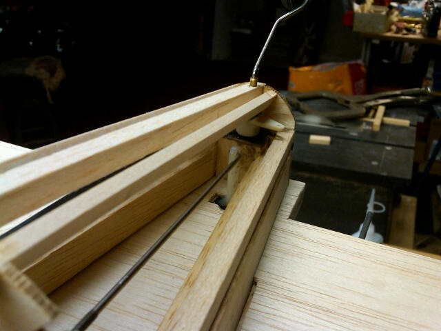
Another view. The pushrod is nice and straight to the elevator. The Sig elevator horn is perfect for this plane.
This shows the amount of up available with the horn and linkage.
Here is the extra set of stringer per Brian's plan for the vent.
In order to clear the rudder horn, the side stringer needed to be cut back and a bulkhead piece put in.
Lower fuse all framed out, ready for sheeting.
Here is the elevator pushrod going in as the stab is trial fit with linkage hooked up.
Stab in place with elevator linkage and rudder horn visible.
Another view. The pushrod is nice and straight to the elevator. The Sig elevator horn is perfect for this plane.
This shows the amount of up available with the horn and linkage.
Here is the extra set of stringer per Brian's plan for the vent.
In order to clear the rudder horn, the side stringer needed to be cut back and a bulkhead piece put in.
Lower fuse all framed out, ready for sheeting.
01-21-2016, 07:55 PM
#20
Thread Starter
Quote | |
| <hr> | |
Worked on the rudder hinges. Lined up the hinge line per the plans and
all seems to work well with the slight deflection of the lower leading
edge of the rudder. All starting to come together now. Need to start
rounding edges of the appendages and sheet the lower fuse now.
I
added 5/8 x 1/4 balsa doublers on each side of F14's. This area
doesn't seem especially strong to me. Better now. Also don't like how
the tops of the F14's where they go into the stab are wider than the
rounded shape of the fuse. It's kind of odd. Curious on what others have
done in this area when they shape the fuse to the stab.
Rudder in place all hinged up.
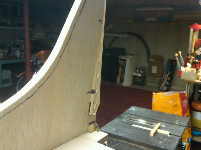
Here's the leading edge deflection.
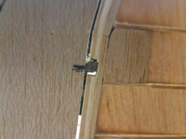
Upper hinge. Robart 1/8 hinge point.
Here is the lower hinge point. Slot cut in with the dremel table saw to get to the correct hinge line depth.
01-22-2016, 07:41 PM
#21
Thread Starter
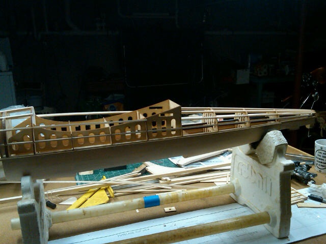
[HR][/HR] Sheeted the bottom of the fuse per the instruction. Put in the saddle sheeting also. Installed my servo rails and servos. Hooked up the push rods and checked all. Put the wing and tail feathers on to have a look. Also stuck the cowl on. Thinking I might build the upper deck out of balsa rather than use the plastic. Haven't decided as of yet.
This rear area is a PITA to do. LOL
Sheeted the wing saddle area.
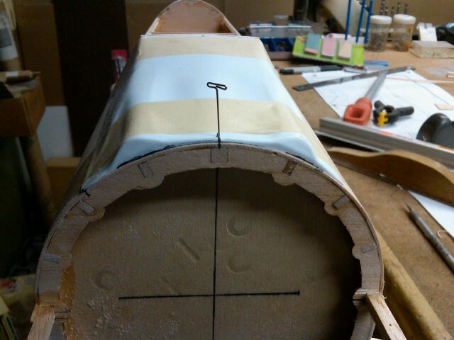
I marked the cowl center line on the firewall before I installed it. Much easier to line up the engine.
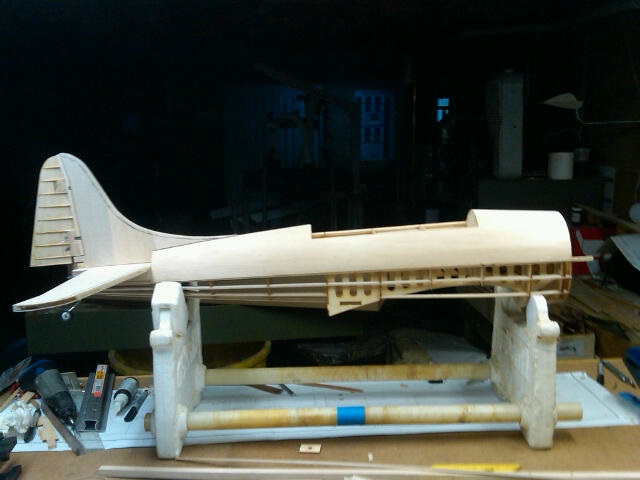
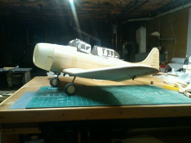
Wing and tail feathers on for a "look"!
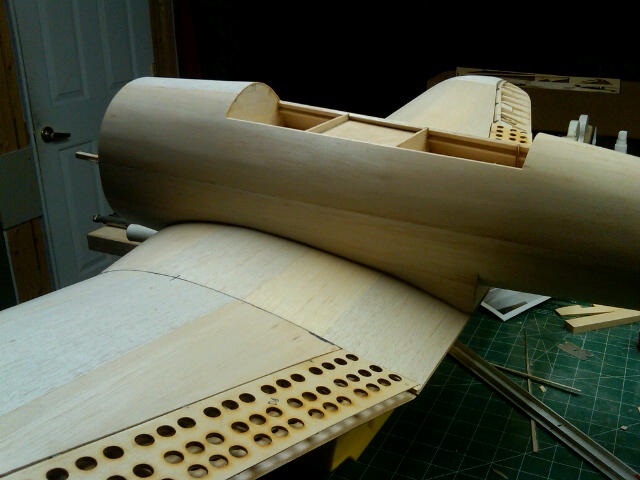
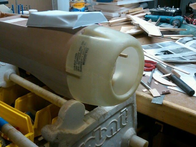
Nice cowl but not a fan of the plastic upper deck.
This rear area is a PITA to do. LOL
Sheeted the wing saddle area.
I marked the cowl center line on the firewall before I installed it. Much easier to line up the engine.
Wing and tail feathers on for a "look"!
Nice cowl but not a fan of the plastic upper deck.
01-24-2016, 05:50 PM
#23
Thread Starter
[HR][/HR] Did a little work today. I trimmed and fitted the front deck and now I've decided to go with it. I was able to get it fitted well and like the results. I found that the front lined up well, the back was not level with the cockpit bulkhead. I added a 5/32 piece of balsa to the plastic upper deck rear then sanded it down level with the cockpit bulkhead. Fitted the wing, checked alignment, and then drilled F22 for the mounting bolts. I used two nylon 1/4 x 20 socket head screws to mount the wing. Using these allows the heads of the bolts to be inside the holes of the middle flap so the flap closes with no issue.
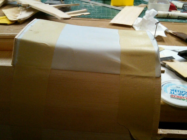
Front of deck fitted. Not much room for gaps underneath the plastic so I'm not worried about reinforcing it. Glassing it might actually take it out of the shape I need but I could put some glass then tape it down on the fuse over some wax paper.
Side of deck trimmed and sanded thin on the edge for a closer fit to the fuse.
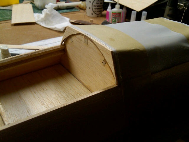
Piece of 3/32 balsa glued on the back of the deck. The rear of the deck was at an angle with the left side almost even with the bulkhead and the right side off about 1/16.
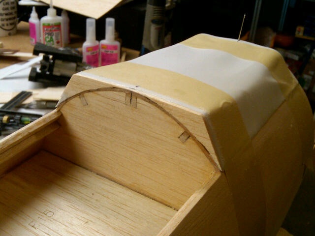
Balsa sanded down level with the bulkhead. You can see the corner in the left with the plastic just exposed while the right side has about 1/16 worth of thickness.
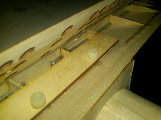
Socket head bolts in the hold down plate. This picture also shows the torque rods for the dive brakes.
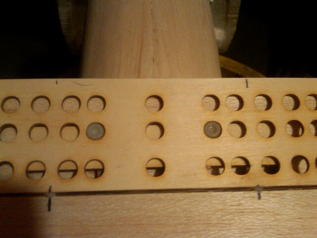
Here is the main middle flap closed with the bolt heads in the flap holes.
Front of deck fitted. Not much room for gaps underneath the plastic so I'm not worried about reinforcing it. Glassing it might actually take it out of the shape I need but I could put some glass then tape it down on the fuse over some wax paper.
Side of deck trimmed and sanded thin on the edge for a closer fit to the fuse.
Piece of 3/32 balsa glued on the back of the deck. The rear of the deck was at an angle with the left side almost even with the bulkhead and the right side off about 1/16.
Balsa sanded down level with the bulkhead. You can see the corner in the left with the plastic just exposed while the right side has about 1/16 worth of thickness.
Socket head bolts in the hold down plate. This picture also shows the torque rods for the dive brakes.
Here is the main middle flap closed with the bolt heads in the flap holes.
01-24-2016, 05:50 PM
#24
Thread Starter
[HR][/HR] Put the gear down and set it down on my cleaned bench (thank god, it needed a cleaning up!). Leveled the wing bottom and then started checking the fuse. Like Mike, I found I have a slight twist to the fuse but nothing that can't be overcome pretty easily. It is less than 3/32 over the entire length. I suspected this with the wing bolted snug, there is more space on the right side of the saddle up by the leading edge than the left. This really shouldn't post a problem with some sanding of the saddle. A little sanding on the stab saddle and all will be straight and level all the way through.
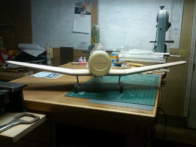
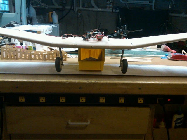
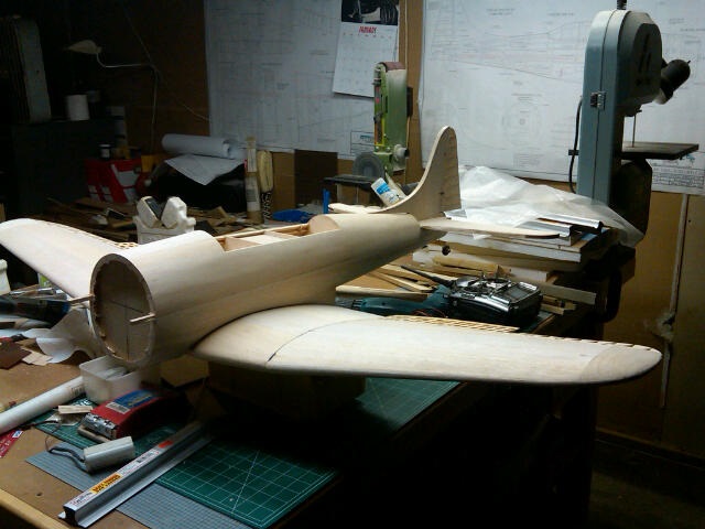
The gear legs angle is greater than the prototype but at least the wheels are on the outside of the gear leg. I can live with it.
It's got that short, stout, look doesn't it.
The gear legs angle is greater than the prototype but at least the wheels are on the outside of the gear leg. I can live with it.
It's got that short, stout, look doesn't it.
01-25-2016, 08:43 PM
#25
Thread Starter
[HR][/HR] Finished squaring off the wing and leveling all the flight surfaces. I had to sand some areas of the wing saddle some and realized the sheeting over the main spar was high leaving a hump and causing the wing not to sit down on the saddle correctly so the sheeting got sanded to an nice airfoil without the hump! LOL
Once the wing dowel plate was epoxied in place, I bolted the wing up and started checking the level of the wing bottom section, cockpit rails, and stab saddle. A little sanding was necessary on the stab saddle but all leveled out.
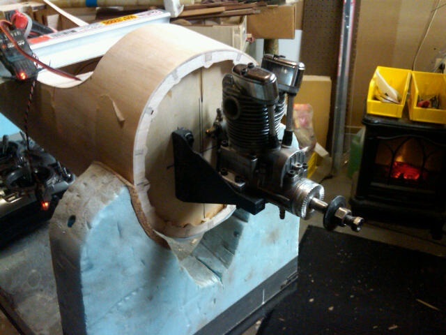
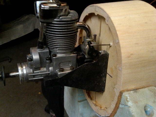
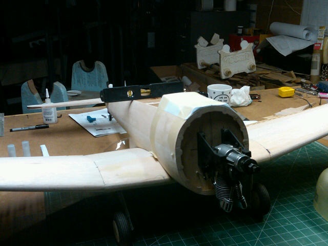
I mounted the engine and then moved the throttle servo from the back rails to the side of ply wing saddle in the first bay. A short 5" pushrod connects the servo to the throttle arm. Of course, when I went to remove the motor to start on the balsa cowl ring, I realized that I installed the motor mount centered on the horizontal when I needed to mount the engine rails on the center. So I had to redrill the holes by 2/10 of an inch.
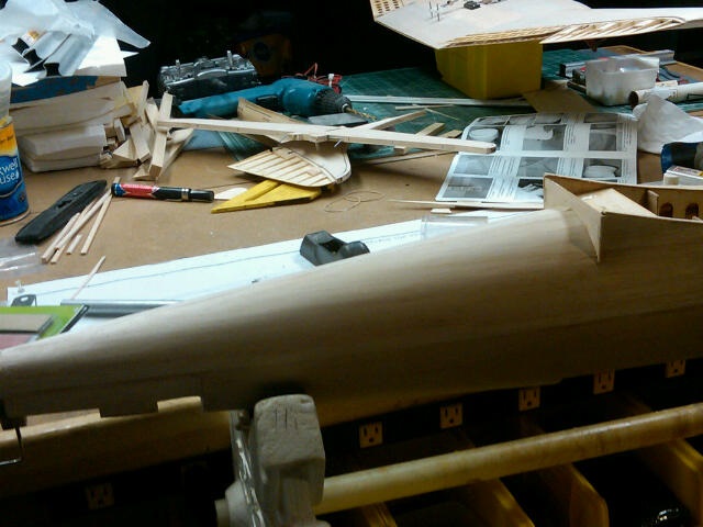
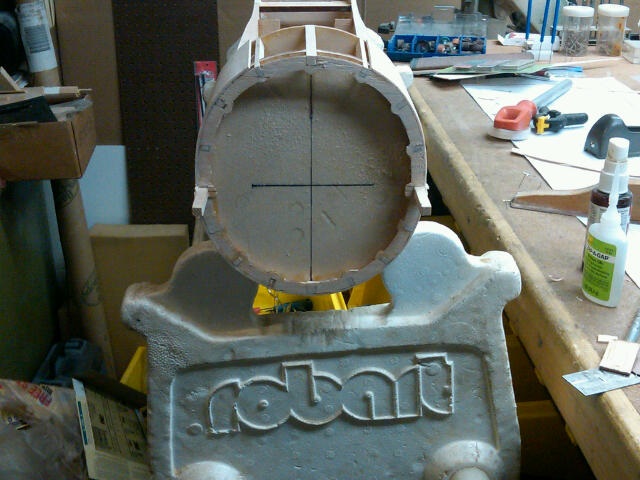
Put the 1/2 balsa pieces all around the front of the fuse and sanded it down even with the sides then rounded the leading edge. Got out my 2" sanding drum on the drill and smoothed out the inside of all the balsa pieces. Once I was happy with the shape I cut with a razor saw the width of the maple blocks and epoxied them to the ply firewall. I will shape them and narrow them where they show but preferred having a wider mount than a narrow one.
Cut out the canopies and found that while the instructions have you sand the top sheeting flat with the rear bulkhead, they don't tell til later in the instructions that you need to put sheeting back in the rear corners for the rear canopy to fit with balsa underneath in. So I added those pieces and rounded them out.
Engine mounted on the firewall. Saito .72
Mini JR servo for throttle mounted up in the front bay of fuse.
Push rod coming through the firewall.
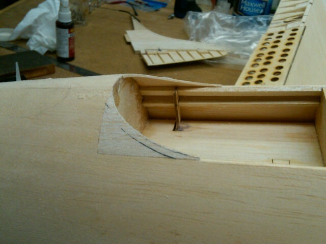
I had to put in these two rounded areas to clear the torque rods for the dive brakes.
After the bottom of the wing center section was checked for level, the cockpit area also showed level.
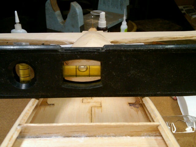
Close up shot of the level on the cockpit rails.
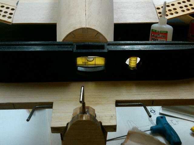
Stab also level on it's saddle.
Balsa added to the rear of gunner's cockpit area.
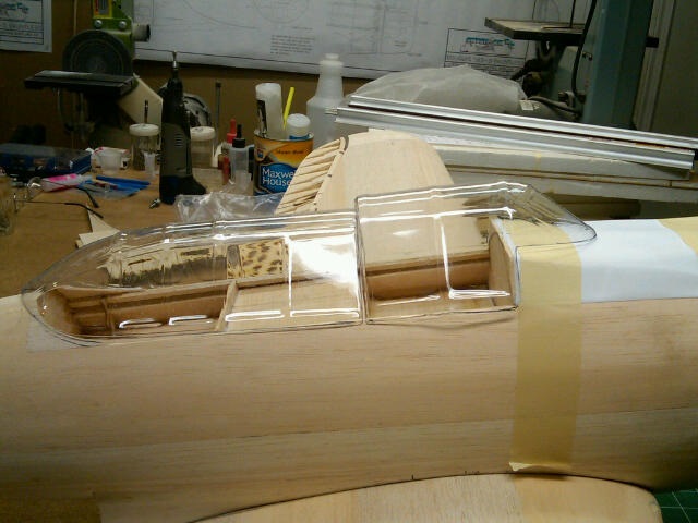
Canopies cut rough cut out and put on the fuse for the hell of it! You can see the rounded balsa at the back of the gunner's cockpit.
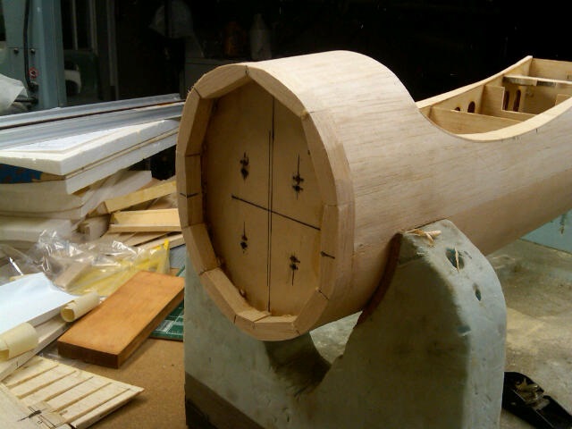
1/2" balsa glued on to front and rough shaped to fuse
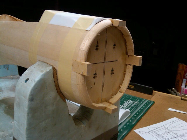
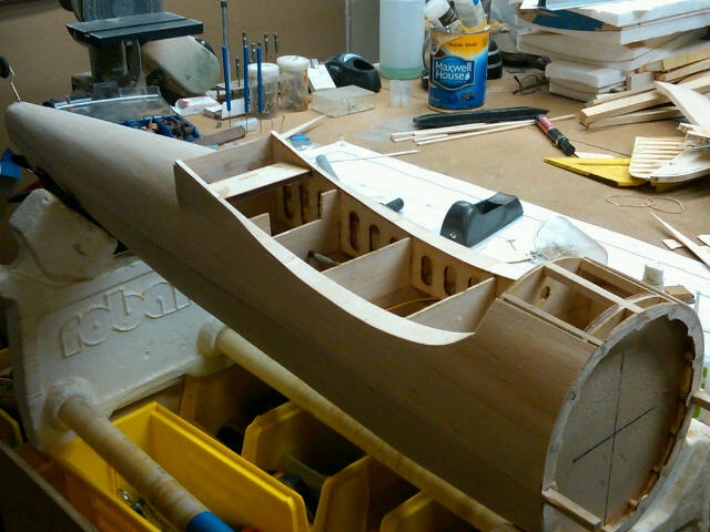
Maple blocks to mount cowl in place. They will be shaped and cleaned up to look much better. Inside of balsa cowl ring sanded out with a 2" drum. You can also see the four extra holes drilled just below the others to put the engine properly on center.
Once the wing dowel plate was epoxied in place, I bolted the wing up and started checking the level of the wing bottom section, cockpit rails, and stab saddle. A little sanding was necessary on the stab saddle but all leveled out.
I mounted the engine and then moved the throttle servo from the back rails to the side of ply wing saddle in the first bay. A short 5" pushrod connects the servo to the throttle arm. Of course, when I went to remove the motor to start on the balsa cowl ring, I realized that I installed the motor mount centered on the horizontal when I needed to mount the engine rails on the center. So I had to redrill the holes by 2/10 of an inch.
Put the 1/2 balsa pieces all around the front of the fuse and sanded it down even with the sides then rounded the leading edge. Got out my 2" sanding drum on the drill and smoothed out the inside of all the balsa pieces. Once I was happy with the shape I cut with a razor saw the width of the maple blocks and epoxied them to the ply firewall. I will shape them and narrow them where they show but preferred having a wider mount than a narrow one.
Cut out the canopies and found that while the instructions have you sand the top sheeting flat with the rear bulkhead, they don't tell til later in the instructions that you need to put sheeting back in the rear corners for the rear canopy to fit with balsa underneath in. So I added those pieces and rounded them out.
Engine mounted on the firewall. Saito .72
Mini JR servo for throttle mounted up in the front bay of fuse.
Push rod coming through the firewall.
I had to put in these two rounded areas to clear the torque rods for the dive brakes.
After the bottom of the wing center section was checked for level, the cockpit area also showed level.
Close up shot of the level on the cockpit rails.
Stab also level on it's saddle.
Balsa added to the rear of gunner's cockpit area.
Canopies cut rough cut out and put on the fuse for the hell of it! You can see the rounded balsa at the back of the gunner's cockpit.
1/2" balsa glued on to front and rough shaped to fuse
Maple blocks to mount cowl in place. They will be shaped and cleaned up to look much better. Inside of balsa cowl ring sanded out with a 2" drum. You can also see the four extra holes drilled just below the others to put the engine properly on center.