


My new beast
 07-14-2018, 01:26 PM
#26

Thread Starter
Thanks fo the info guys ! Yea I agree w Jerry I don’t think the blanks would be a good idea here, I may just go for a flashing led ? So much to think about and plan. And honestly I have been into this hobby for about 5 yrs now and the electric aspect still makes me nervous. I am going to continue researching and gathering info and then decide how to proceed
Cheers Guys. Mark
Cheers Guys. Mark
Last edited by Markocaster; 07-14-2018 at 01:30 PM.
 07-14-2018, 01:54 PM
#27
Thread Starter
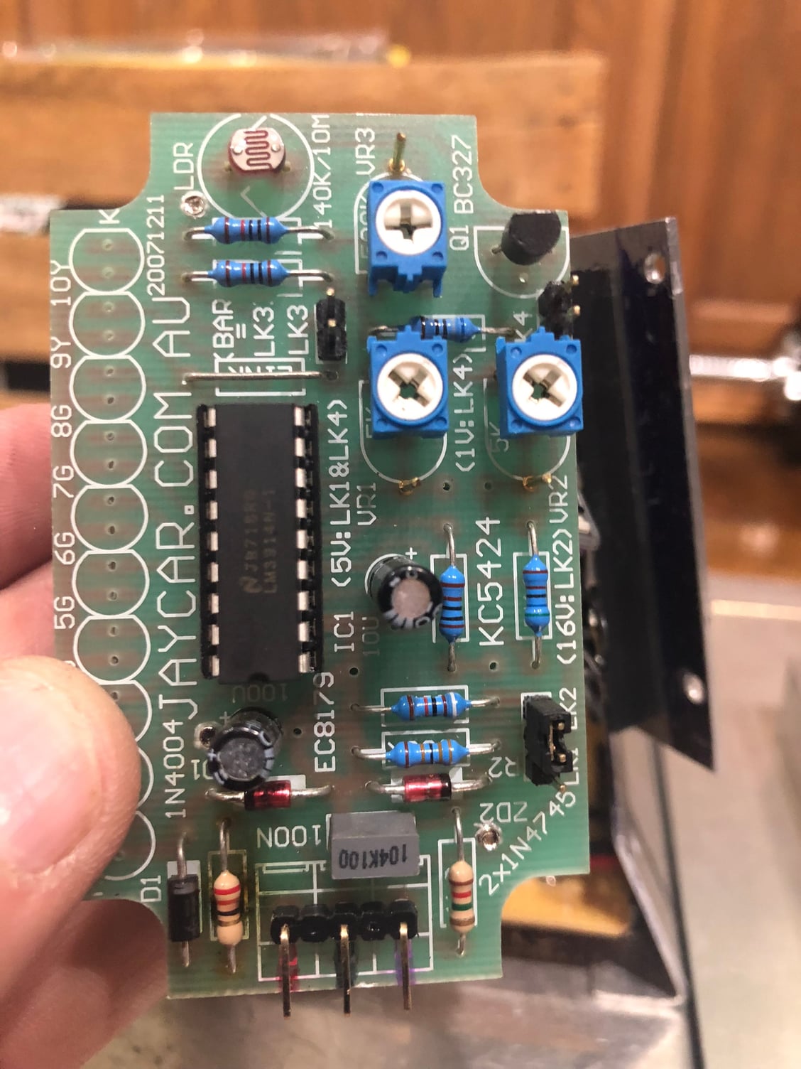
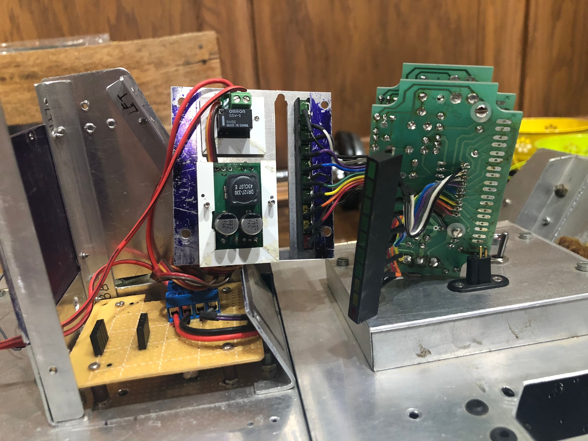
I was going though the papers that came with the tank. Originally it had a voltage regulator this was removed I believe as were the original speed controllers a vantec rdfr23 was added and some wiring reworked. Here are a few photos.
The iriginal schematic, then the newer one. And finally the vantec.

Original schematic
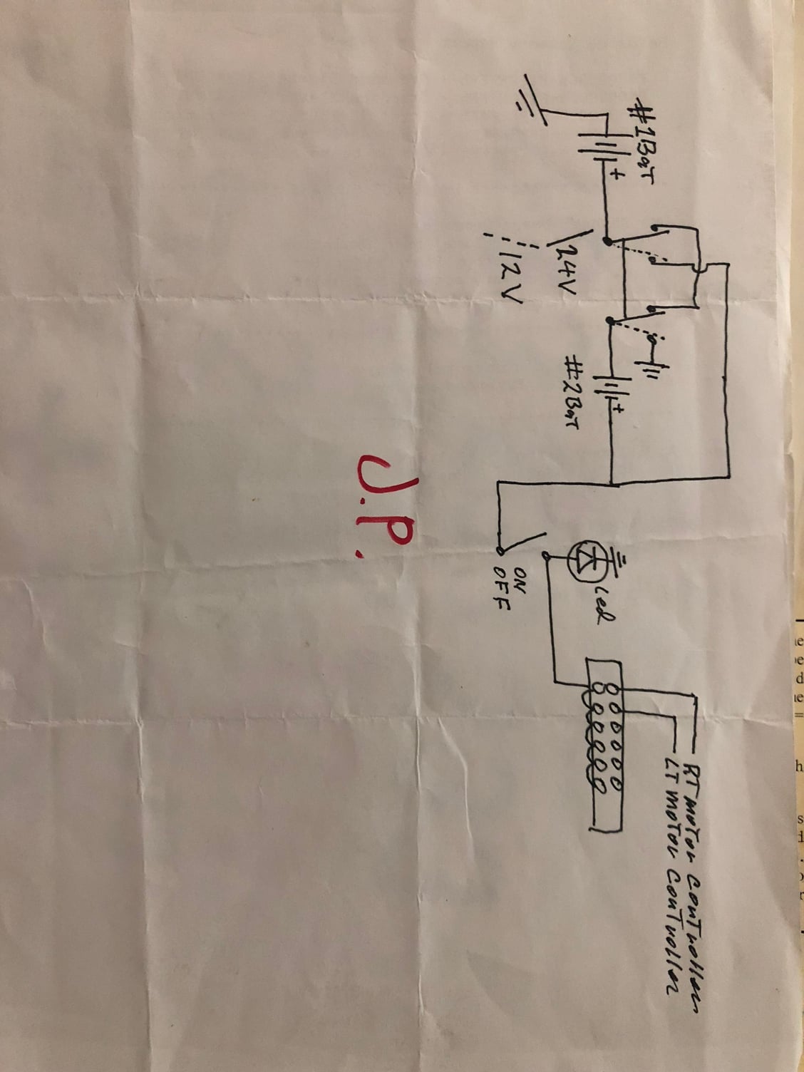
New schematic
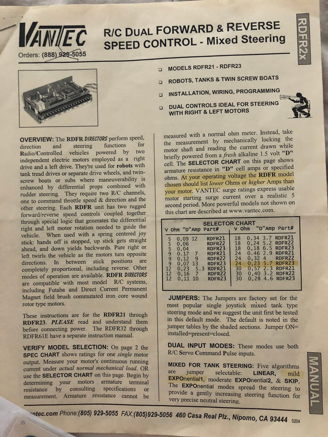
Vantec soeed controller
The iriginal schematic, then the newer one. And finally the vantec.
Original schematic
New schematic
Vantec soeed controller
07-14-2018, 07:22 PM
#28
I was going though the papers that came with the tank. Originally it had a voltage regulator this was removed I believe as were the original speed controllers a vantec rdfr23 was added and some wiring reworked. Here are a few photos.
The iriginal schematic, then the newer one. And finally the vantec.
Original schematic
New schematic
Vantec soeed controller
The iriginal schematic, then the newer one. And finally the vantec.
Original schematic
New schematic
Vantec soeed controller
issue with the Futaba system I was using it with and never returned to it. The Vantec guys were helpful but my patience wasn't.
I'd go with an IBU3 type or a OP- board. Let me know if I can help. I no longer have any IBU3 boards left, I only have a few IBU2 types and those probably not for that long.
Jerry
07-15-2018, 08:10 AM
#29
I tried to get a Vantec controller to work as well in a 1/6 project with no luck. I use Sabertooth Speed controllers now, they are super easy to install and set up.
https://www.dimensionengineering.com...sabertooth2x25
Bob
https://www.dimensionengineering.com...sabertooth2x25
Bob
07-15-2018, 08:53 AM
#30
I'm using both a sabertooth and an IBU2 Pro in my 1/6 Hetzer, running on 6S lipo batteries for the motors and a 7.4 lipo for the IBU. Then the FPV system uses 3S lipo, so one of these days I'll get step downs and put everything on the 6S. But for now it works great, and the IBU is really versatile. Not only does it give me machine gun sound, rotation and LED flash for the remote MG-34, I also get cannon sound and the circuit for barrel recoil pulls the trigger on the .50 caliber paintball cannon, with everything in sync. I'm just using the TPA amp and have enough room for twin 4 inch speakers, it sounds great with plenty of volume, and the RVC gives me volume control at the TX, though right now I just use it for volume on engine sounds. The i10 also gives me the option to use a slide switch for volume so I might add the secondary sounds later, but for now they're adjustable under a rear hatch. I could also use it for lights, but the Hetzer only had the notek and a convoy light so I'm not sure it's worth it. Both would barely show up in daylight anyway. Oh yeah, I'm also using the smoke circuit on the IBU and believe it or not, a decent stock smoker provides all I need. I might still try one of my custom jobs (the ones Normand taught me) but for now they work fine.
If you go just 3S lipo you could drive everything on that tank with an IBU2 Pro (with a TPA), get great sound and have your choice of motor or servo for elevation and traverse.
If you go just 3S lipo you could drive everything on that tank with an IBU2 Pro (with a TPA), get great sound and have your choice of motor or servo for elevation and traverse.
 07-15-2018, 09:02 AM
#31
John I hate to say it this way but.... most models from that era were quilt work jobs where guys threw diverse components together in order to get a functioning model. This was obviously before the integrated systems we see today.
My recommendation is you strip out everything you want to replace from the model, and you do want to replace just about everything and make a clean, new sanitary installation of a current more state of the art system. In the long run you will be happier and you'll have a more manageable system. If you need to swap motors for ones that give better performance at lower speeds you should consider that as well.
Whenever I buy a model, except new ones, I reconcile myself to the fact that I'm buying the bones and it's up to me to make certain those bones are good ones and revitalize the model.
Jerry
07-15-2018, 04:23 PM
#32
Thread Starter
John I hate to say it this way but.... most models from that era were quilt work jobs where guys threw diverse components together in order to get a functioning model. This was obviously before the integrated systems we see today.
My recommendation is you strip out everything you want to replace from the model, and you do want to replace just about everything and make a clean, new sanitary installation of a current more state of the art system. In the long run you will be happier and you'll have a more manageable system. If you need to swap motors for ones that give better performance at lower speeds you should consider that as well.
Whenever I buy a model, except new ones, I reconcile myself to the fact that I'm buying the bones and it's up to me to make certain those bones are good ones and revitalize the model.
Jerry
My recommendation is you strip out everything you want to replace from the model, and you do want to replace just about everything and make a clean, new sanitary installation of a current more state of the art system. In the long run you will be happier and you'll have a more manageable system. If you need to swap motors for ones that give better performance at lower speeds you should consider that as well.
Whenever I buy a model, except new ones, I reconcile myself to the fact that I'm buying the bones and it's up to me to make certain those bones are good ones and revitalize the model.
Jerry
 07-24-2018, 05:41 PM
#33
Thread Starter
As it isn’t running now I decided to take a peek inside at the electrical components on top. The gun is the only thing my spektrum radio will operate now? so I am poking around as I read up on how to proceed. My hats off to those of you who have this electric thing dialed in it makes my head spin. I am looking into a saber tooth speed control, I have an ibu2 pro, unused.All the electric components seen here will be removed.
it makes my head spin. I am looking into a saber tooth speed control, I have an ibu2 pro, unused.All the electric components seen here will be removed.Last edited by Markocaster; 07-24-2018 at 05:44 PM. Reason: Spelling
07-24-2018, 06:57 PM
#34
Thread Starter
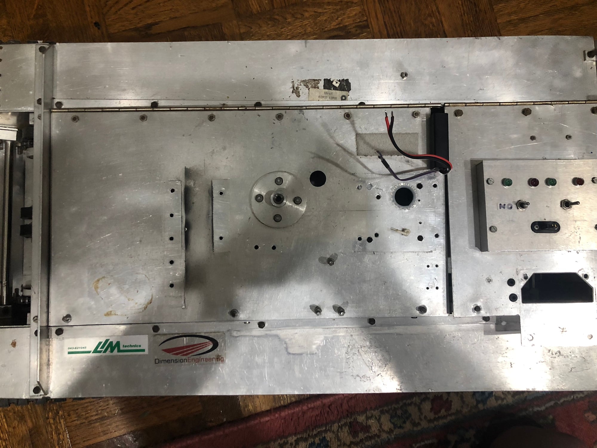
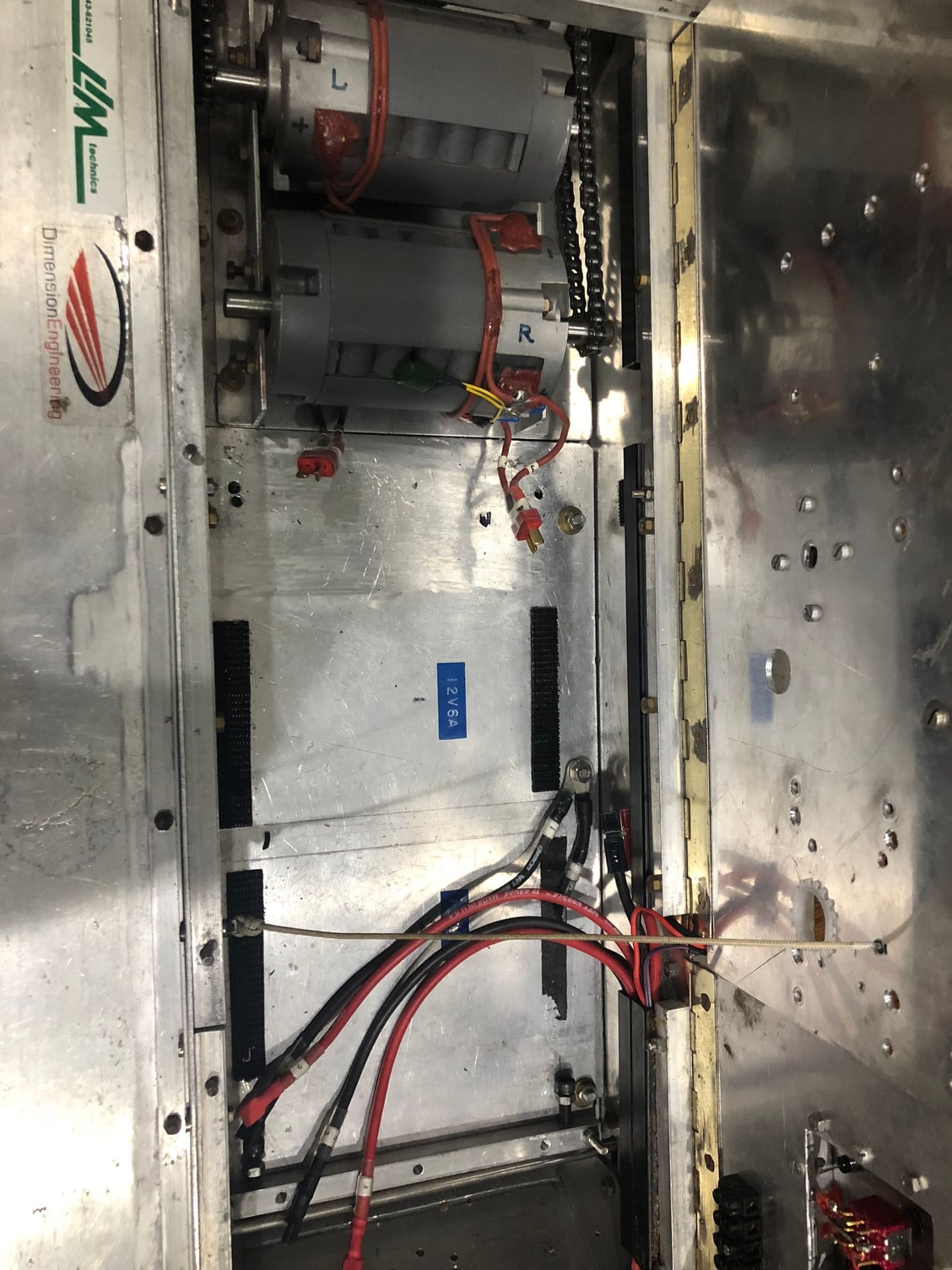
:0 well it’s out. No more gun thing
i left the basic wires to the motors and the on switch and removed the case containing the other bits. The vantec came out easily. I hope I can still use these motors with the future electrics
07-25-2018, 08:21 AM
#35
If you run the IBU on 12 volts, you won't need the saber-tooth. The only reason I'm using the Sabertooth in the hetzer is because those are 24 volt Motors and the IBU won't handle 24 volts.
07-25-2018, 08:30 AM
#36
Thread Starter
you guys are all probably rolling your eyes at me going what’s he doing lol 😂 but this is my mission ! I will no mater how long it takes figure out this aspect of the machine ! I have lots to learn. Cheers fellas and thanks for all the kind words. I am sure you will see lots more happy and frustrated posts in the future.
Cheers. mark
Last edited by Markocaster; 07-25-2018 at 08:57 AM.
07-25-2018, 09:44 AM
#37
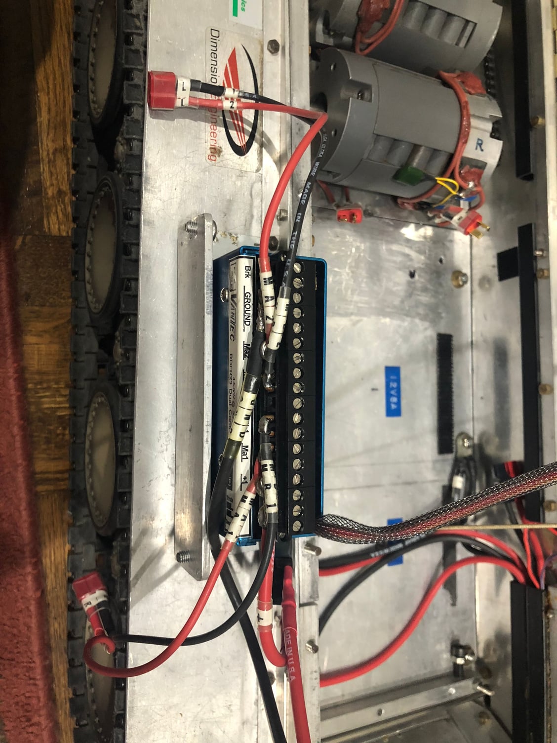
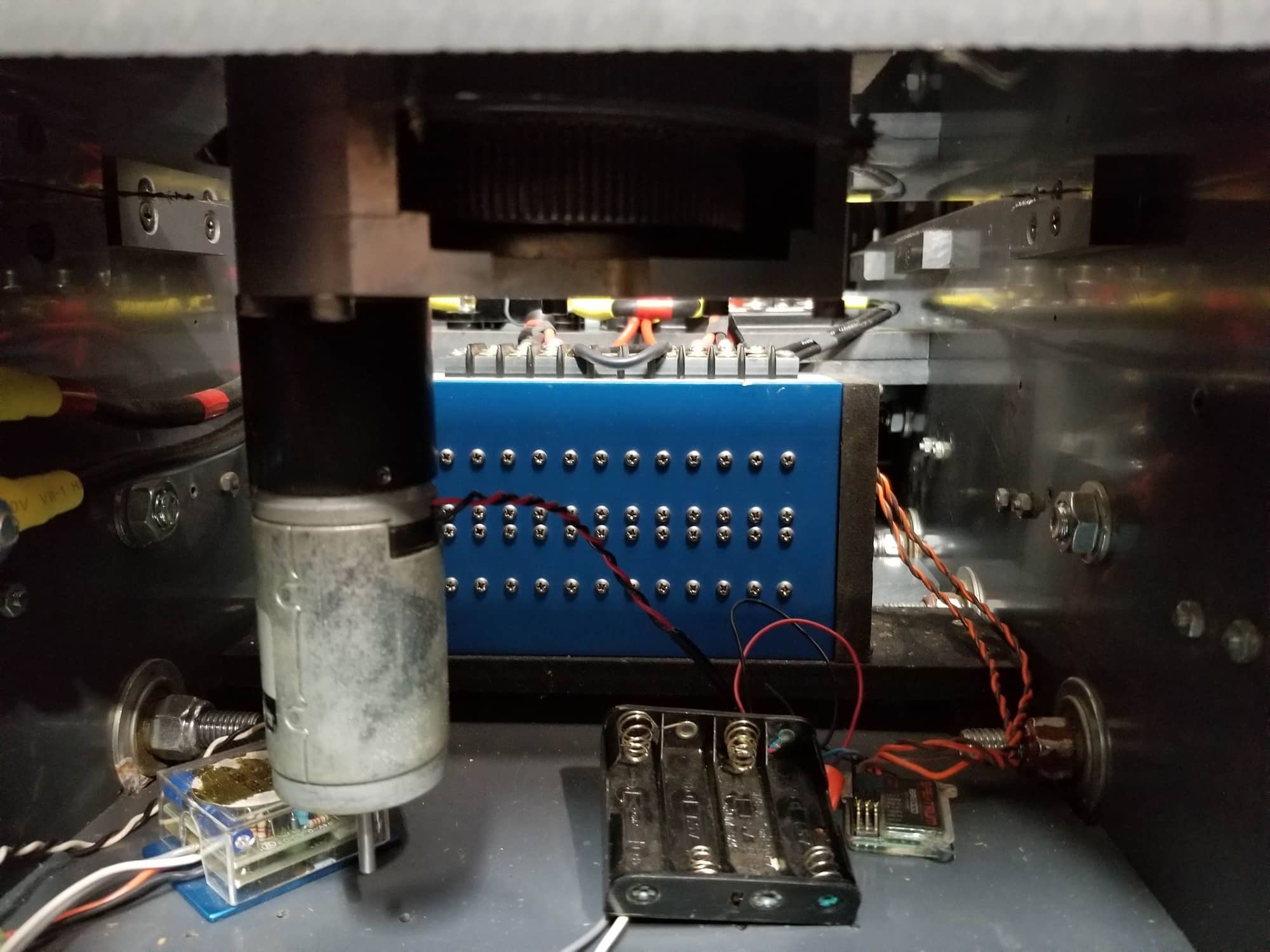
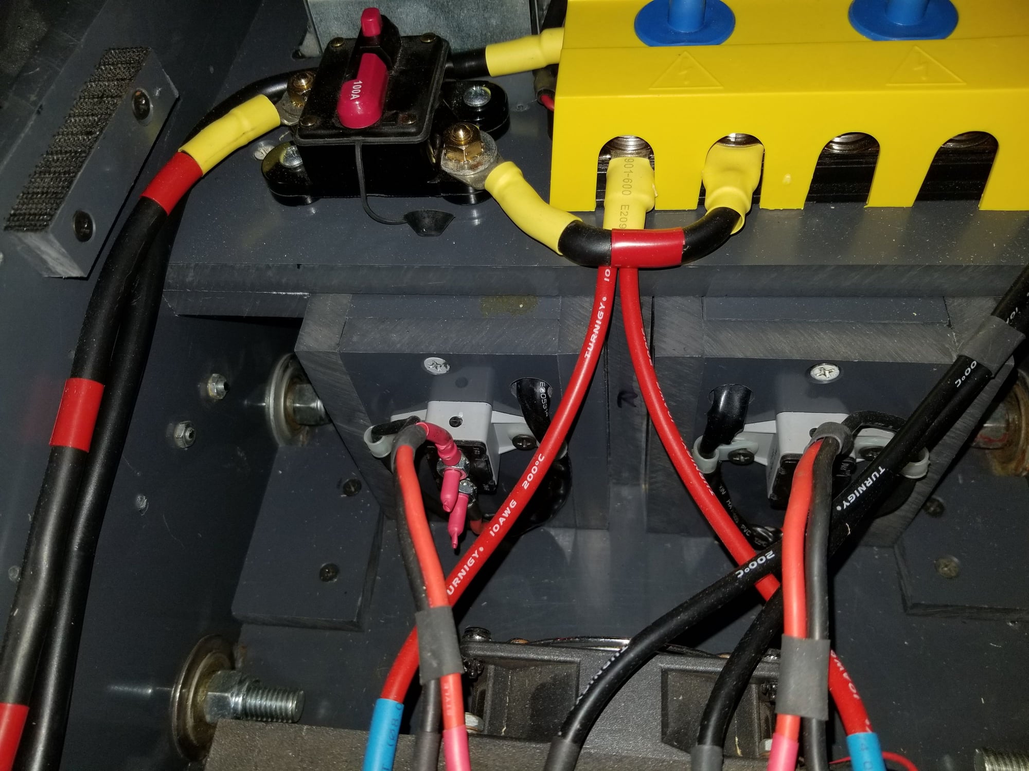
It's funny that you guys have issues with the Vantec RDFRs. I've had a Vantec RDFR38E in my 1/6th KV-2 for years and it runs great, but it is also directly connected to my radio receiver without a tanks control board of any sort. I'm using it with older 1st gen Spektrum systems (DX6i and DX5e) with either a BR6000 or an AR6000 receiver. I have both. I have fully enclosed the RDFR and put a fan on it just in case. Yes, everything is just a little over built, but that's the way I like it... Battery leads are 4AWG splitting into two 8AWG leads to connect two 24V 5000mah 6S LiPOs. 100A breaker protects the main power. Motor leads are 10AWG going through a 50A breakers mounted to the backs of the motor enclosures (I have blown 30A fuses during a stall in a previous iteration of this build). Power leads to RDFR are (2) 8AWG wires. Battery connectors are XT150s. I've been wanting to integrate an Open Panzer TCB into this build, but rather than using a voltage step down I would just directly power the TCB from a lower voltage pack since my motors run at 24V also.
RDFR38E mounted vertically

Shot from the front showing the fan.
Battery leads are 4AWG splitting into two 8AWG leads to connect two 24V 5000mah 6S LiPOs. 100A breaker protects the main power. Motor leads are 10AWG going through a 50A breakers mounted to the backs of the motor enclosures (I have blown 30A fuses during a stall in a previous iteration of this build). Power leads to RDFR are (2) 8AWG wires. Battery connectors are XT150s. I've been wanting to integrate an Open Panzer TCB into this build, but rather than using a voltage step down I would just directly power the TCB from a lower voltage pack since my motors run at 24V also.RDFR38E mounted vertically
Shot from the front showing the fan.
07-25-2018, 10:16 AM
#38
Thread Starter
It's funny that you guys have issues with the Vantec RDFRs. I've had a Vantec RDFR38E in my 1/6th KV-2 for years and it runs great, but it is also directly connected to my radio receiver without a tanks control board of any sort. I'm using it with older 1st gen Spektrum systems (DX6i and DX5e) with either a BR6000 or an AR6000 receiver. I have both. I have fully enclosed the RDFR and put a fan on it just in case. Yes, everything is just a little over built, but that's the way I like it... Battery leads are 4AWG splitting into two 8AWG leads to connect two 24V 5000mah 6S LiPOs. 100A breaker protects the main power. Motor leads are 10AWG going through a 50A breakers mounted to the backs of the motor enclosures (I have blown 30A fuses during a stall in a previous iteration of this build). Power leads to RDFR are (2) 8AWG wires. Battery connectors are XT150s. I've been wanting to integrate an Open Panzer TCB into this build, but rather than using a voltage step down I would just directly power the TCB from a lower voltage pack since my motors run at 24V also.
RDFR38E mounted vertically
Shot from the front showing the fan.
Battery leads are 4AWG splitting into two 8AWG leads to connect two 24V 5000mah 6S LiPOs. 100A breaker protects the main power. Motor leads are 10AWG going through a 50A breakers mounted to the backs of the motor enclosures (I have blown 30A fuses during a stall in a previous iteration of this build). Power leads to RDFR are (2) 8AWG wires. Battery connectors are XT150s. I've been wanting to integrate an Open Panzer TCB into this build, but rather than using a voltage step down I would just directly power the TCB from a lower voltage pack since my motors run at 24V also.RDFR38E mounted vertically
Shot from the front showing the fan.
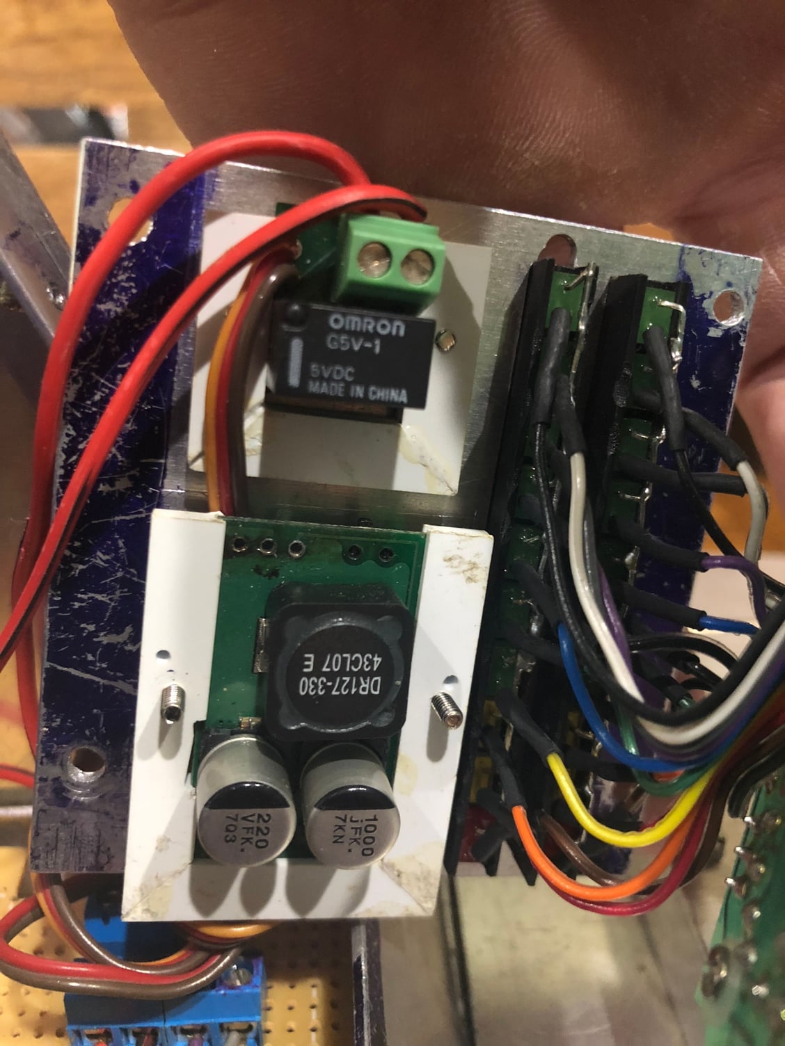
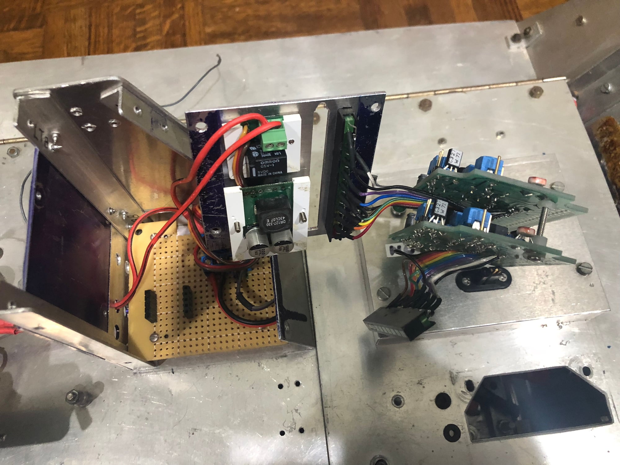
thanks for this reply. So I am taking from this I can just run the vantec as is w the radio. I started looking at that and noticed
that after removing the original “board” I no longer have a power supply for
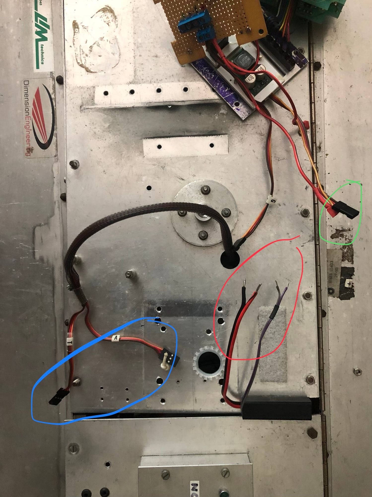
The receiver. The green is he old power cable for the receiver
the red circle is the left over wires from the on off switches.
And the blue are the 2 connectors for the speed controller.
Am I correct that I just need to wire the receiver into the wires in the red circle.
Thanks guys.
Last edited by Markocaster; 07-25-2018 at 10:34 AM.
07-25-2018, 11:08 AM
#39
Thread Starter
I found my servo tester. Hooked it up and the batteries for the tank and radio (spektrum) &...nothing lol damn thought it would at least move. Obviously im
missing something? How does one test a speed controller , the motors, etc ? I suspect it’s the remaining wire and how it’s hooked up? Anyway learning as I go.
missing something? How does one test a speed controller , the motors, etc ? I suspect it’s the remaining wire and how it’s hooked up? Anyway learning as I go.
07-25-2018, 01:41 PM
#40
The RDFR does not have a BEC to provide power for the receiver. As you saw in one of my pics, there was a AA battery pack I was using to power my receiver. After switching to the TCB, the receiver will be using the power from the TCB. You can see the two 4AWG wires in my pic (one black and the other black w/red). The black w/red is my main power and black is ground. The main power goes into the main 100A breaker which acts as my on/off switch. When I push the button it cuts power to the main power bus (fans, motors, RDFR, turret rotation, etc). Since the receiver has its own power source, the receiver has its own on/off switch. So when I power up the tank I turn on the transmitter, then the receiver, and then my main power. You will want a switch to turn on your receiver, but I don't think you should wire the current switch directly to your receiver. The receiver runs on 5V to 9V for most receivers. Connecting it to a full 24V will blow your receiver. The receiver needs either a small battery pack like I'm using or BEC from an IBU/similar device. They also make stand alone BECs that can step 24V down to 5/6V for a receiver. My solution uses a 24V rated breaker that can handle the entire current of the system. I'm sure that tiny little switch cannot be wired as an inline switch the way mine is. The switch wouldn't handle the current. That switch is probably turning on a relay that kicks on the 24V for the motors and the 12V voltage step down.
07-25-2018, 02:06 PM
#41
Thread Starter
The RDFR does not have a BEC to provide power for the receiver. As you saw in one of my pics, there was a AA battery pack I was using to power my receiver. After switching to the TCB, the receiver will be using the power from the TCB. You can see the two 4AWG wires in my pic (one black and the other black w/red). The black w/red is my main power and black is ground. The main power goes into the main 100A breaker which acts as my on/off switch. When I push the button it cuts power to the main power bus (fans, motors, RDFR, turret rotation, etc). Since the receiver has its own power source, the receiver has its own on/off switch. So when I power up the tank I turn on the transmitter, then the receiver, and then my main power. You will want a switch to turn on your receiver, but I don't think you should wire the current switch directly to your receiver. The receiver runs on 5V to 9V for most receivers. Connecting it to a full 24V will blow your receiver. The receiver needs either a small battery pack like I'm using or BEC from an IBU/similar device. They also make stand alone BECs that can step 24V down to 5/6V for a receiver. My solution uses a 24V rated breaker that can handle the entire current of the system. I'm sure that tiny little switch cannot be wired as an inline switch the way mine is. The switch wouldn't handle the current. That switch is probably turning on a relay that kicks on the 24V for the motors and the 12V voltage step down.
cheers
07-25-2018, 03:18 PM
#42
You can take your motor leads and touch them directly to a battery to make sure your motors are actually functional. Doesn't even matter about polarity since it will just turn the motor in reverse if you reverse the polarity. Battery probably doesn't even have to be 24V. A 12V or even a 6V battery would probably move the motors. They would just move slower of course. Back when this tank was made, there weren't as many voltage regulators and batteries available cheaply like now so it looks like the person that built it designed their own electronics package. I like simple connections and wiring I can understand. This tank has a lot of "custom" wiring it seems. Personally if I was troubleshooting it I would break it down as simple as possible, verify functionality, and then build it back up to the way I want it. Keep in mind with the RDFR that when it shows you need to wire two positive leads to it and multiple grounds, that it needs them connected to operate. The RDFR is two H-bridge circuits in a single housing with a mixing circuit built in controlled by an R/C input. You could do all of these things using seperate devices. All Vantec did was put them all in one neat little box. Each H-bridge circuit has it's own positive and negative connections essentially which is why you see two red leads and two black leads on mine. Mine also has a jumper that electrically binds the two ground pins together. I'm guessing Vantec designed the H-bridges this way so that the end user could use smaller gauge wires by running two of them instead of one big one. I wouldn't worry too much about LiPOs until you figure out if everything runs the way it should...
07-27-2018, 08:14 AM
#43
If you plan to use the saber-tooth, you can power your receiver from that. That's the way I did it in my hetzer. The Sabertooth controls the motors which are on the 6-cell LiPO batteries, but the Sabertooth also has a BEC and I'm using that to power the receiver. The IBU has its own separate battery but it doesn't have anything to do with controlling the motors so even if the battery in the IBU dies I won't have to worry about a runaway tank.
07-27-2018, 06:59 PM
#44
Good to hear that the Vantec will work with other systems. I had given Mark some bad info offline from this thread.
It was my understanding that Vantec aimed their RDFR units to work with Futaba's PCM implementation and it would be
problematic with other protocols. This is obviously wrong if a Spektrum system will work.As that can be eliminated as
an issue I agree with others who suspect more fundamental power or wiring issues. I've used stand alone BEC units
in several 1/10 models but usually the one that is incorporated into many brands of brushed motor ESCs - I use an ESC
of that type to control the turret drive.
Jerry
08-07-2018, 12:14 PM
#45
Thread Starter
Hi guys ! It’s been a bit, work and life get in the way of my tank time as I’m sure many of you can relate.
I recieved a box of plugs, wire, new soldering iron & battery tester. I am looking for a replacement 6 pin toggle switch, however I need some assistance.
Would I need an on/on , On/off , on off on. , off on off ? I think on / off ? But really not sure.
So still waiting on a few more parts and a switch and I can begin wiring it up. Cheers
08-07-2018, 06:44 PM
#46
Thread Starter
I actually got it to run today 
I hooked the battery to the main power of the speed controller, then attached my receiver powered by AA batteries and it runs. Forward backwards left and right.
I could use a little wiring advice on switch selection. I have 6 wires + & - for main power to speed controller and then a + & - for each of the motors. So I assume a 6 pole toggle but whitch configuration and how do I wire it. Cheers
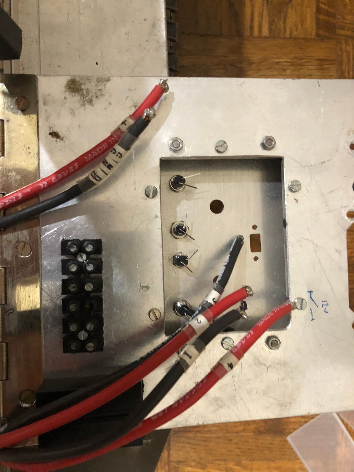
The 6 wires I need to find a toggle for

Testing
I hooked the battery to the main power of the speed controller, then attached my receiver powered by AA batteries and it runs. Forward backwards left and right.
I could use a little wiring advice on switch selection. I have 6 wires + & - for main power to speed controller and then a + & - for each of the motors. So I assume a 6 pole toggle but whitch configuration and how do I wire it. Cheers
The 6 wires I need to find a toggle for
Testing
08-07-2018, 08:27 PM
#47
Marcocaster,
I'm not sure you need a 6 wire switch. But you do want to break the red power wires with a switch. I have had good luck with the Hella marine 100A
like this:
https://www.westmarine.com/buy/hella...BoCzhUQAvD_BwE
The Hellas are not cheap, but they work really well. But any high Amp switch should work. And I think you want just on/off - at least for the main switch.
Your set up appears slightly different, but this may help. I'm using a Sabretooth ESC, but I'd bet the wires are similar for the main motors. You should have a black and red wire from each motor. I recommend each motor should have a fuse to prevent burning up the motors. My project tank motors stall at 80amps, so I put a 60A fuse on each (red wire) of both motor - just under stall to prevent damage to motors (at least that's my logic). The motor wires should plug into the ESC. The ESC should have locations for powering/controlling 2 motors. 2 Red wire (+) terminals and 2 Black wire (-) terminals. Then you will have a black and red wire from your batteries into the ESC. This would be the main power inlet to the ESC. I don't know if your batteries are in series or parallel but the 100A Hella switch would go on the red wire from the battery(or batteries) - to the main power inlet (+) on the ESC. This will give you a positive connect/disconnect of the battery power to ESC. The black wire would not need to go into the switch, but go straight from battery (-) to ESC main (-). The Sabertooth has an overcurrent/Over temp shut down so I don't have a separate fuse for it. The Vantec may need a fuse to protect it - I'm not sure, you should check the literature for that speed controller. The Vantec should have inputs for the receiver wires from the motors as well. You will have two receiver inputs into the ESC, one for speed (Throttle), one for steering (Rudder). The Sabetooth is nice in that you don't need a separate battery for the receiver, the ESC powers it via 5V (as Gary mentioned). But its fine to have a separate pack for the receiver.
Hope that remotely helps?
Best regards, I think you are making progress!
Bob
Last edited by RC_BobM; 08-07-2018 at 08:44 PM.
08-08-2018, 08:00 AM
#48
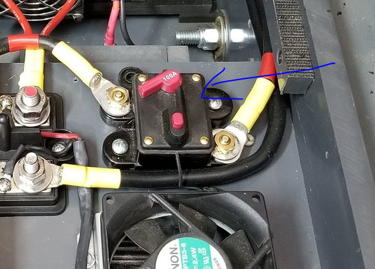
Press the red button to open the breaker.
Glad you got movement out of the tank. It's always a happy milestone in my builds. My Vantec ESC makes the tank very easy to control at both high and low speeds.
I agree with Bob with the motor fuses/breakers. My motors stall at over 100A so I have mine going through a 50A breaker like these:
https://www.ebay.com/itm/BUSSMANN-Sh...53.m1438.l2649
I can grab a pic of my motors breakers and how I have them wired tonight. You can also use fuses (ANL or AGU type), but fuses need to be replaced where I can just reset my breakers if they pop. I don't want the motors to pull anymore than 50A each. My logic is that I don't want to exceed the limits of my ESC and burn it out. Large ESCs like the Vantec are more expensive than motors. At 50A I have 30A of play. Plus if both motors start pulling more than 100A combined, the main breaker will pop to protect from drawing too much current from the batteries. I've been contemplating lowering the main breaker down to 70A to be even safer now that I'm running LiPOs in the tank instead of SLA batteries. Above is my On/Off switch, but it's actually a breaker. The breaker is basically a stereo breaker. I have used the Hella type switches like Bob suggested and they work well too. Plus with the removable key, you can keep people from meddling with it. Lockout/tagout...
I don't have a fuse or a breaker going to the Vantec ESC other than the main breaker since it can handle over 220A on a surge. The main would pop way before that surge could get to the ESC if the batteries could even deliver that.
08-08-2018, 09:07 PM
#49
Derek
Can you share where you got that slick resettable 100A switch / breaker? And the heavy duty bus-bar? I've looked high and low for something like that and not found any like it. Those are very cool. I like the resettable fuses <your link above> as well, beats the replaceable automotive type.
You have a very slick set up there that others can learn from.
Bob
08-08-2018, 09:50 PM
#50
Motor breaker mounting. Main breaker in "on" position. Buss bar cover in place.
I had the cover off of mine in the first pics, but the Buss bar is here and it does come with the cover: https://www.ebay.com/itm/Dual-7-poin...sid=m570.l1313
Breaker is from Ebay, but Amazon has them also:
https://www.amazon.com/Asdomo-12V-24...4v+breaker+24v
Just search on the amps you want and voltage with breaker on Ebay (IE: 24v breaker 100a) and they will show up. I mounted the breakers to the backs of the motor "pods". The motors didn't really have a good mounting method so I mounted them in a pod. The pod actually moves back and forth in a track of sorts to be able to re-tension the motor to drive shaft chains. The actual track tension is done in the front of the vehicle and it's ultra simple, but I don't have to tension my tracks often because they are so stiff and heavy. They never come of the drive sprockets.