


1/7 Scale Blackburn Buccaneer All Composite Scratch Build
 02-18-2021, 01:18 AM
#651
Yes, battered and bruised but he's OK now I believe...

 03-09-2021, 12:41 PM
#652

Just over a month since I lost the first version, and v2 is progressing well.
I'm working on a lot of the smaller parts first, going through each one and correcting design issues that I noted during the initial build, and others that I have spotted on a review of the CAD files. On the control surfaces, I re-positioned the spars to give the correct hinge installation location and added a hinge pin guide tube to make installation of the pin easier.
For all the Airex skins, I have reduced the glass weight down to 0.75oz, and the unsupported glass is now just 2 layers of 3oz + 1 layer of 6oz. For the highly curved inlets, I reduced that down to just 3 layers of 3oz and that saved a significant weight on each part.
Hysol 9642 is being used for all assembly bonds.
Redoing the main gear doors, I made 3 sets in an attempt to get the detail reproduced and to reduce the weight of the parts.
I have made new molds for the speedbrake drag links to ensure that they fit the cutout in the fuselage and speedbrake correctly (there was no gap allowance on the first ones), plus I have worked out how to reproduce domed headed rivets in the mold, rather than just simple flat topped cylinders.
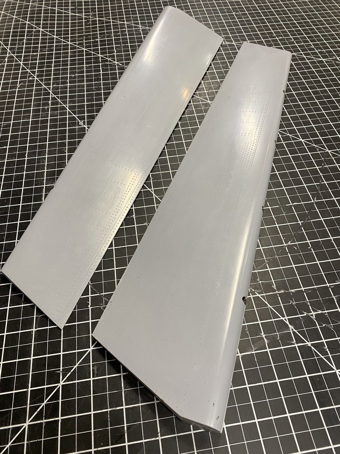
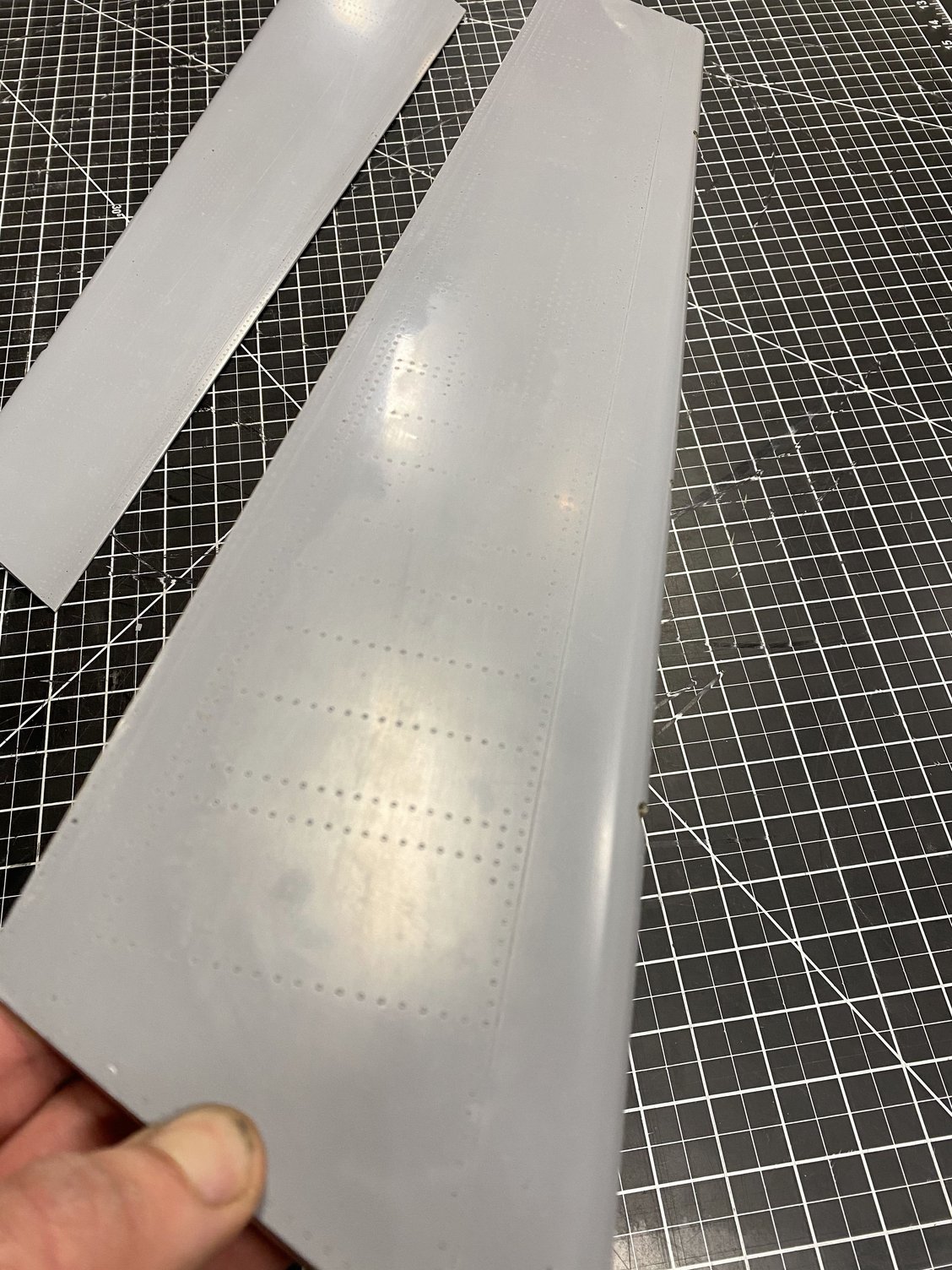
I have also remade the aileron molds to correct the surface detail, going from raised rivets to flush rivets.
I sent off the wing joiner blade spars to be machined out of AL 7075 and they have just arrived.
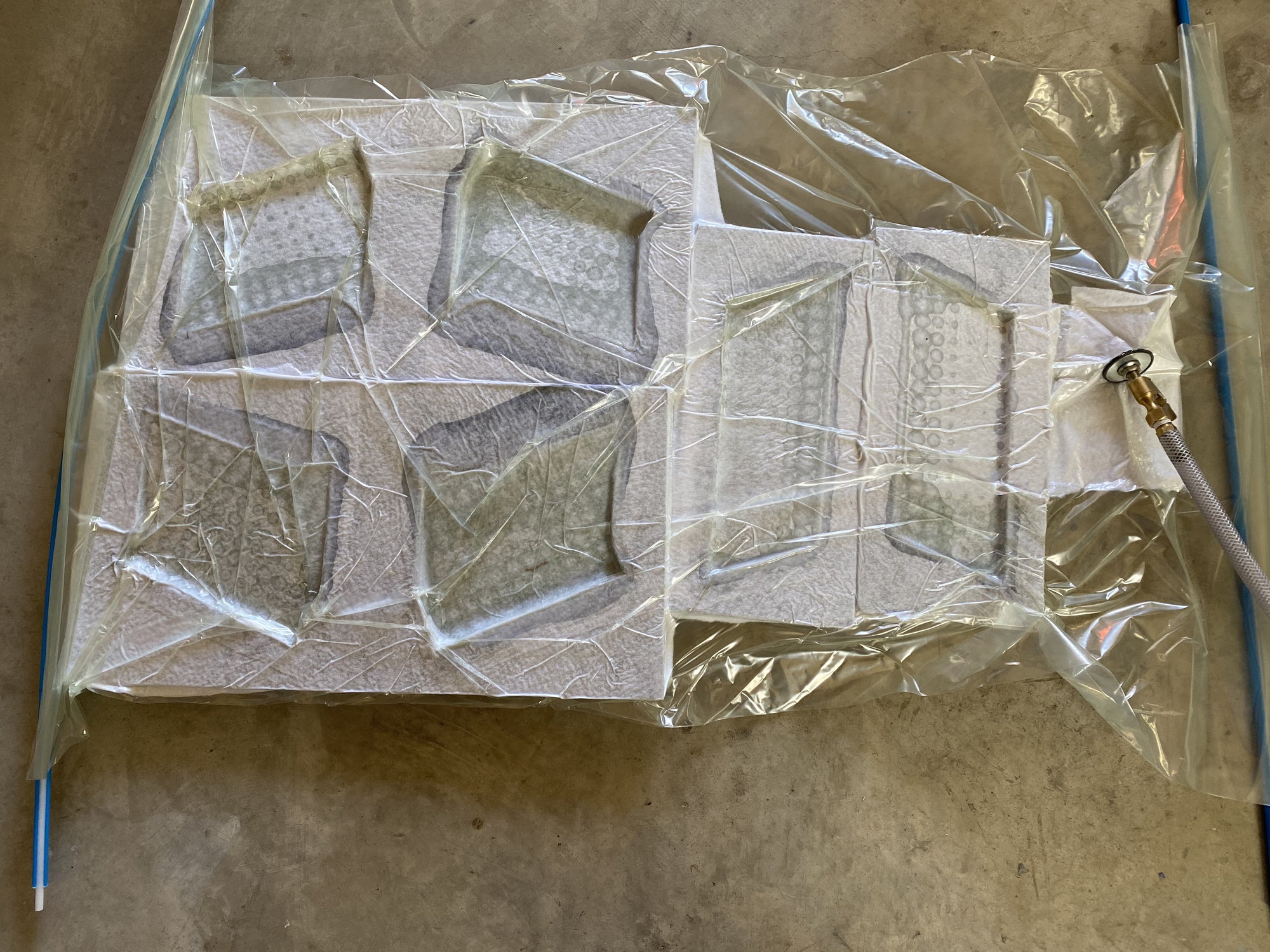
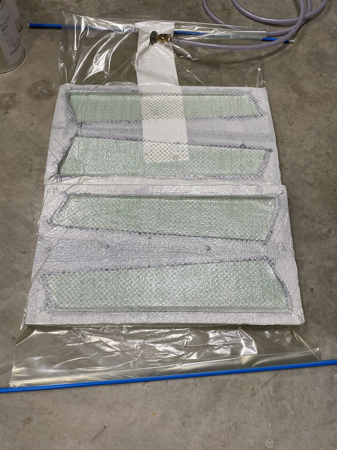
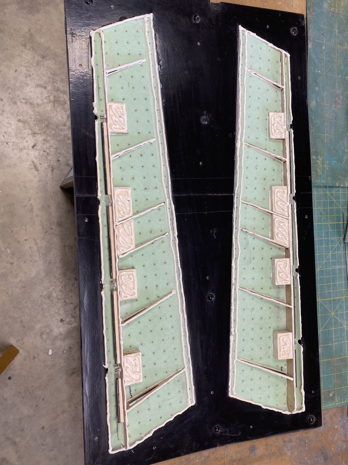
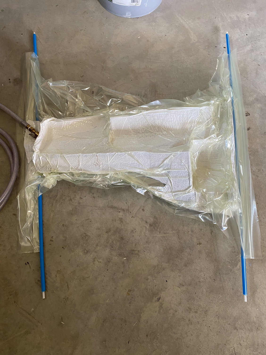
Inner Flaps and Rudder skins vacuum bagged

Inner Flap internal structure
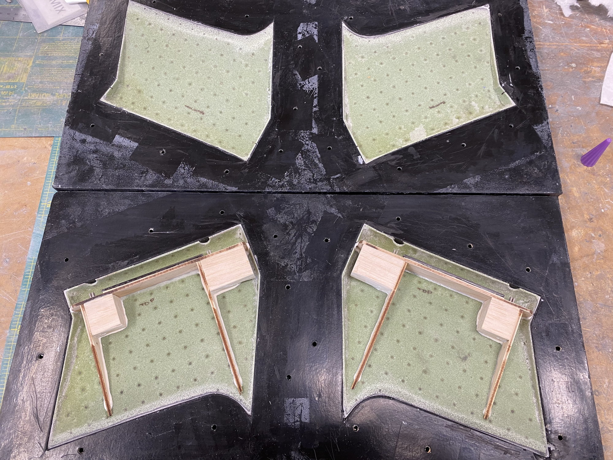
Inner Flaps internal structure

Rudder internal structure ready to close up
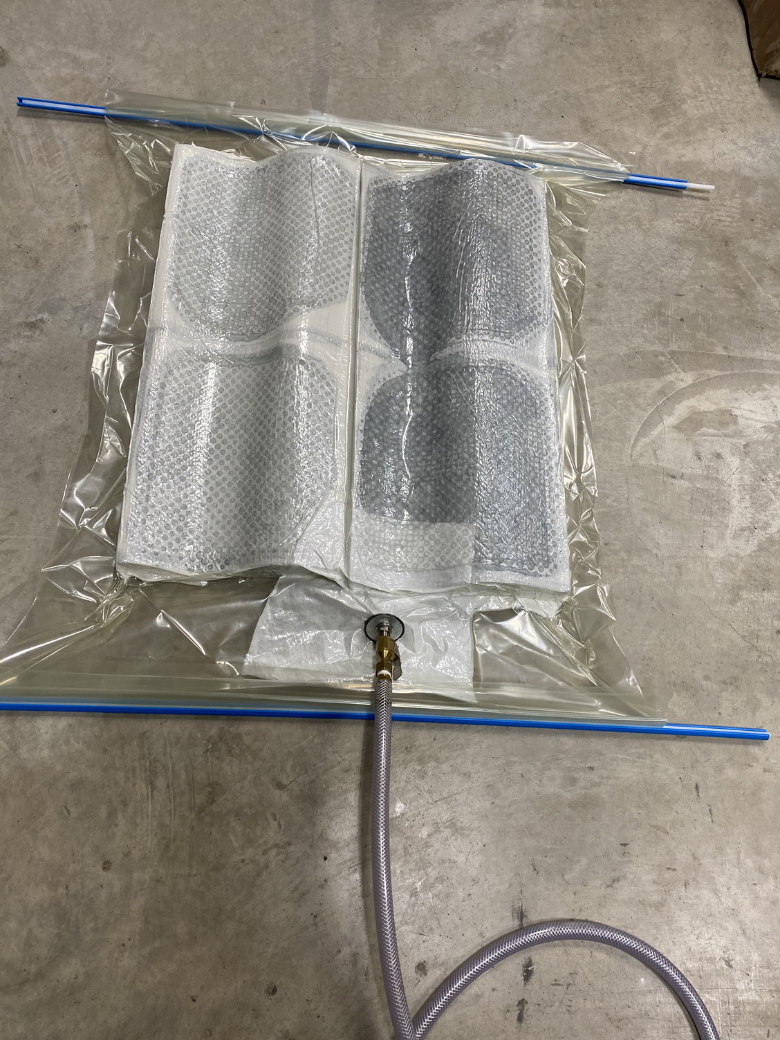
Main gear doors vacuum bagged
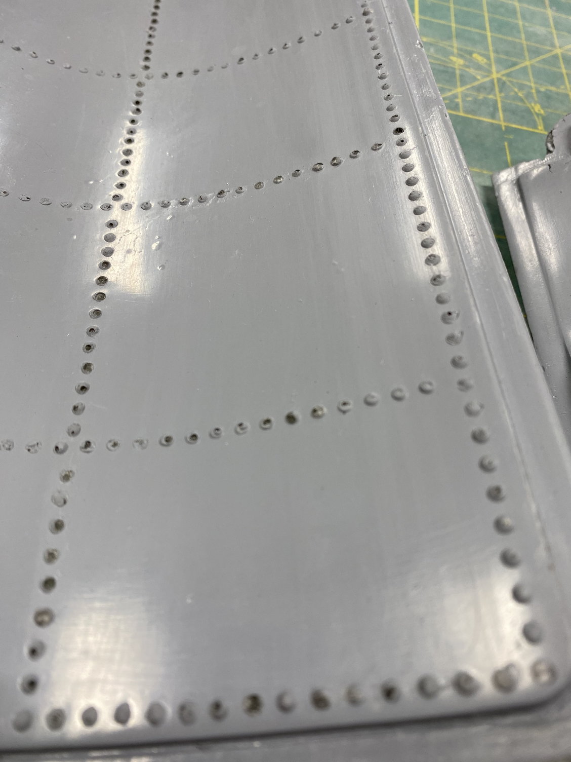
Main gear doors inner surface domed rivets

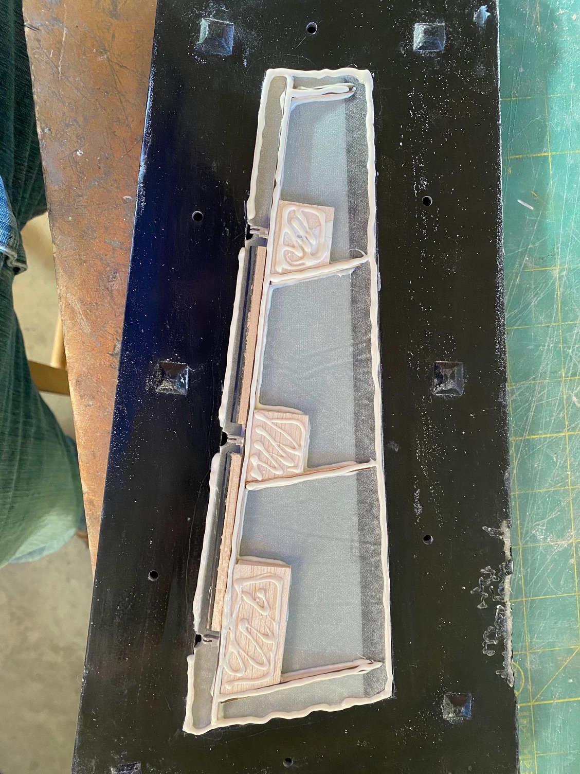
New speedbrake drag link molds in work

Speedbrake drag links with domed rivets
Tailplane flap internal structure ready to close up
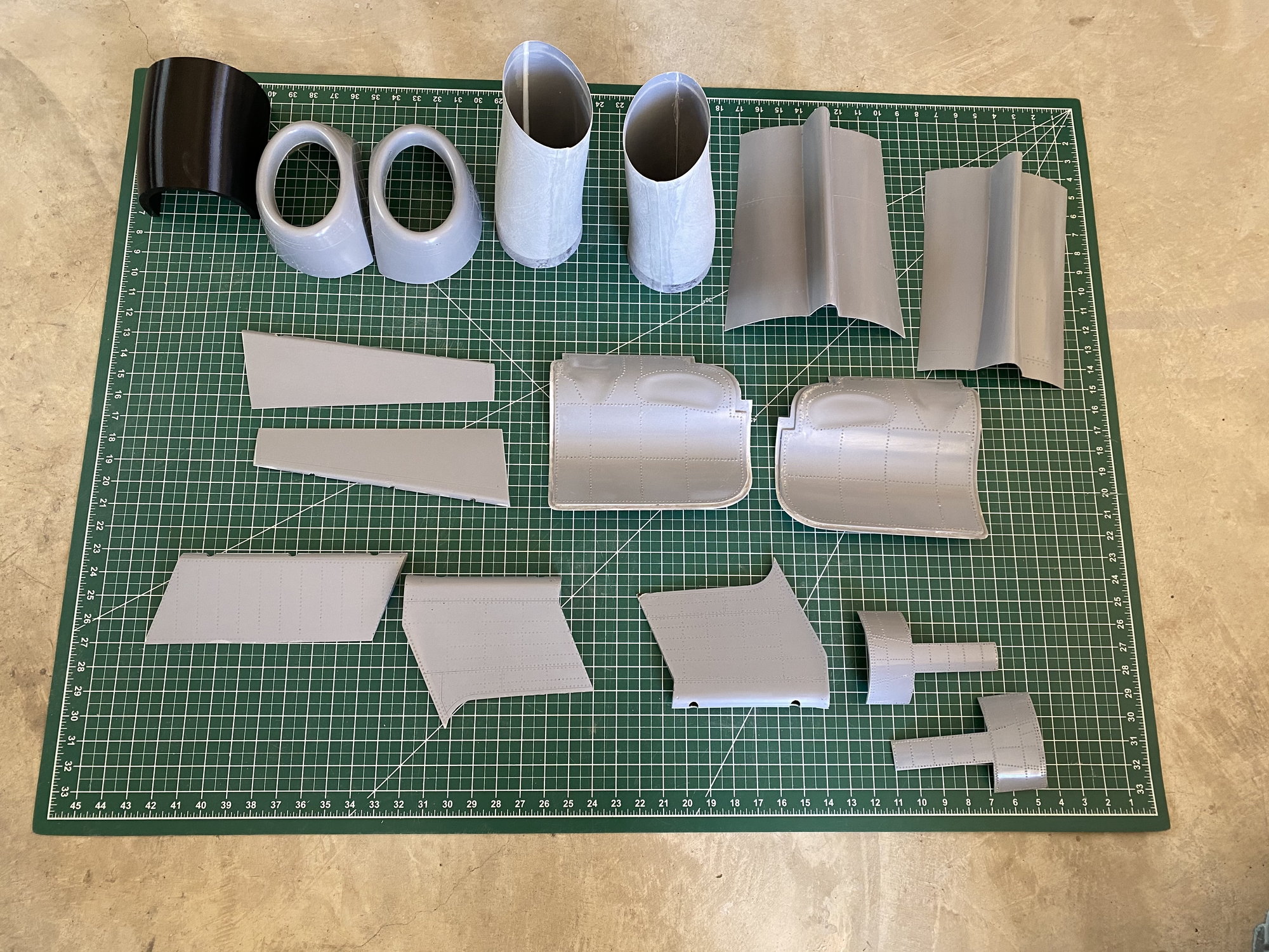
Parts completed so far.
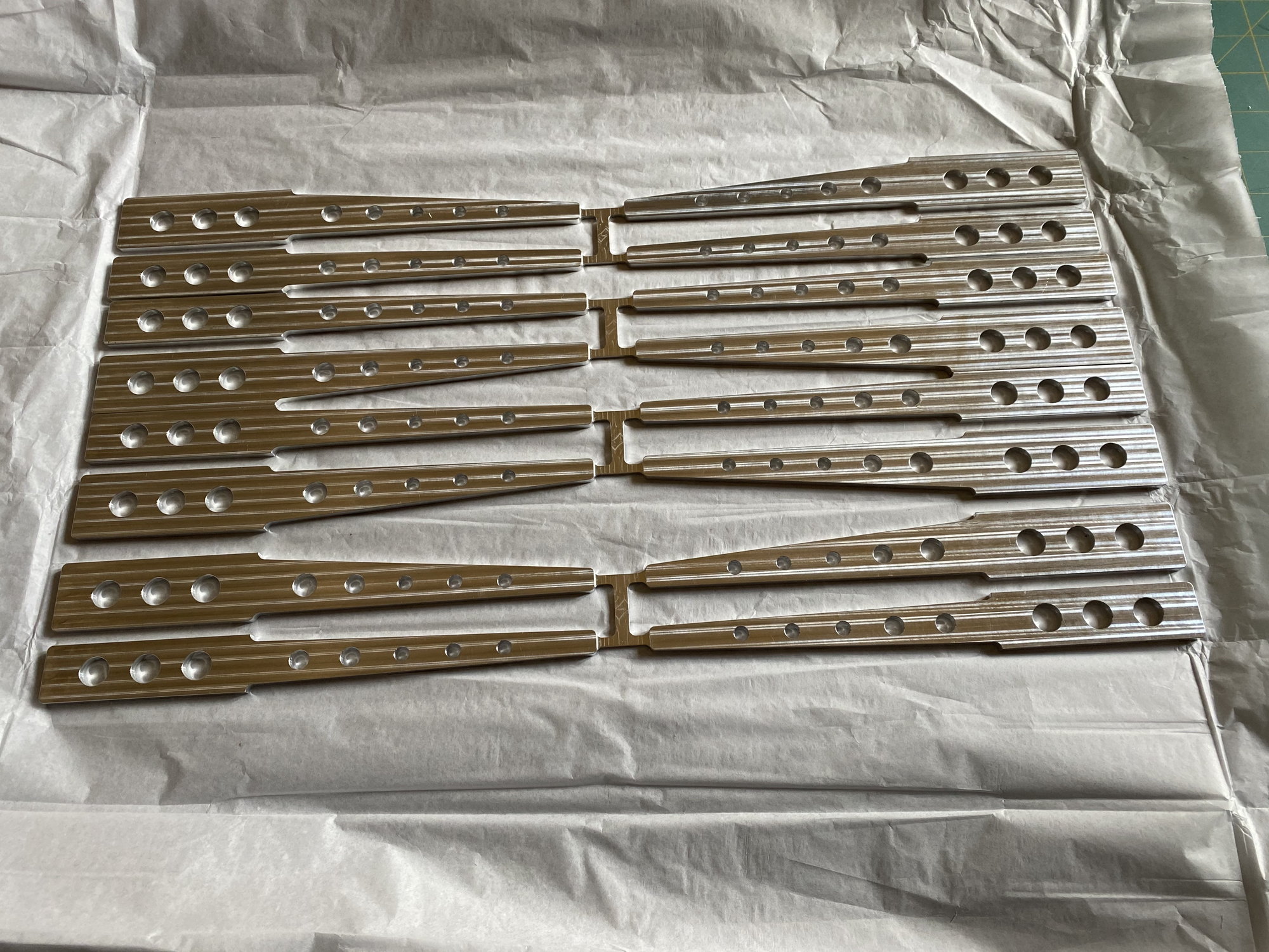
4 sets of machined wing joiner blade spars
Paul
I'm working on a lot of the smaller parts first, going through each one and correcting design issues that I noted during the initial build, and others that I have spotted on a review of the CAD files. On the control surfaces, I re-positioned the spars to give the correct hinge installation location and added a hinge pin guide tube to make installation of the pin easier.
For all the Airex skins, I have reduced the glass weight down to 0.75oz, and the unsupported glass is now just 2 layers of 3oz + 1 layer of 6oz. For the highly curved inlets, I reduced that down to just 3 layers of 3oz and that saved a significant weight on each part.
Hysol 9642 is being used for all assembly bonds.
Redoing the main gear doors, I made 3 sets in an attempt to get the detail reproduced and to reduce the weight of the parts.
I have made new molds for the speedbrake drag links to ensure that they fit the cutout in the fuselage and speedbrake correctly (there was no gap allowance on the first ones), plus I have worked out how to reproduce domed headed rivets in the mold, rather than just simple flat topped cylinders.
I have also remade the aileron molds to correct the surface detail, going from raised rivets to flush rivets.
I sent off the wing joiner blade spars to be machined out of AL 7075 and they have just arrived.
Inner Flaps and Rudder skins vacuum bagged
Inner Flap internal structure
Inner Flaps internal structure
Rudder internal structure ready to close up
Main gear doors vacuum bagged
Main gear doors inner surface domed rivets
New speedbrake drag link molds in work
Speedbrake drag links with domed rivets
Tailplane flap internal structure ready to close up
Parts completed so far.
4 sets of machined wing joiner blade spars
Paul
Last edited by JSF-TC; 03-09-2021 at 01:04 PM.

The following users liked this post:
Auburn02 (03-09-2021)

 10-17-2021, 01:23 PM
#655
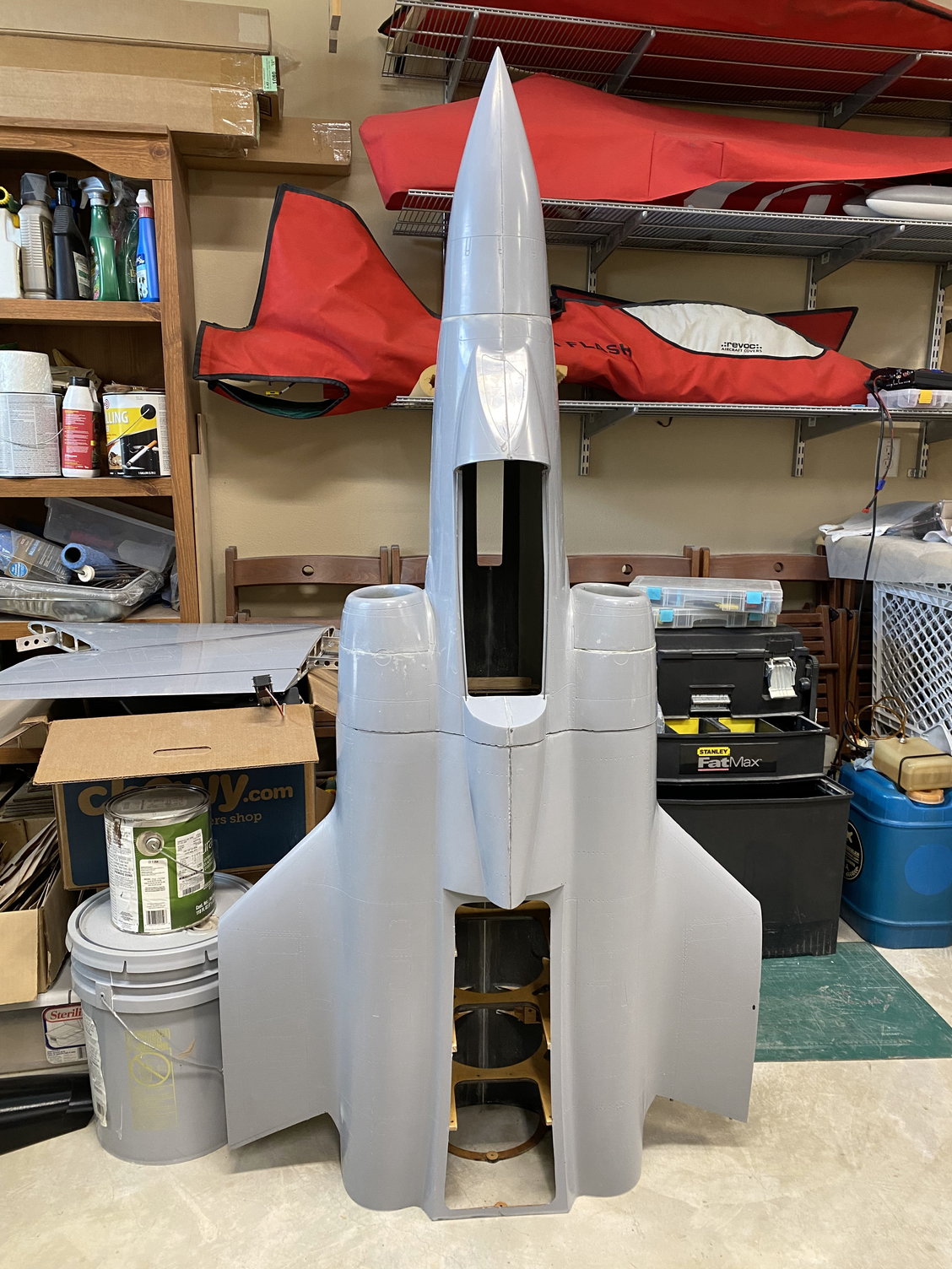
I haven�t posted much on this thread since the loss on first flight of model #1 8 months ago, but I�ve been working steadily (if slowly) on building model #2.
The build of #2 hasn�t looked a lot different that all the previous build pictures, but it is been changed significantly internally. The majority of the internal structure has been re-designed, nothing drastic, but incorporating lessons learned from the first one plus correcting design errors spotted since it was first drawn. For the tailplane and flaperons, I switched to using glass/ foam skins rather than just glass skins, so new structure had to be designed to accommodate the thicker skins.
New molds were made for the flaperons, correcting the previous raised rivets to now flush rivets.
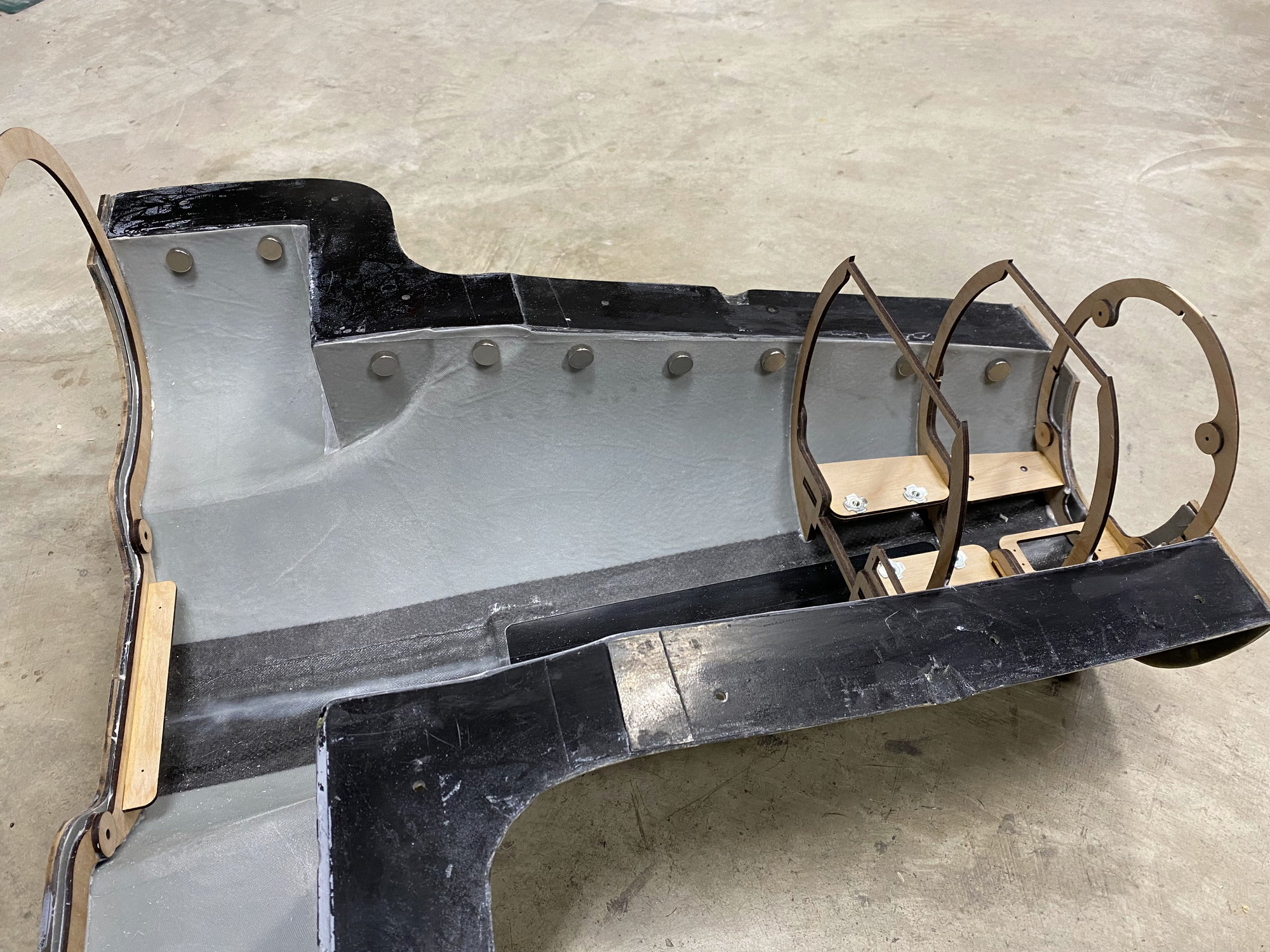
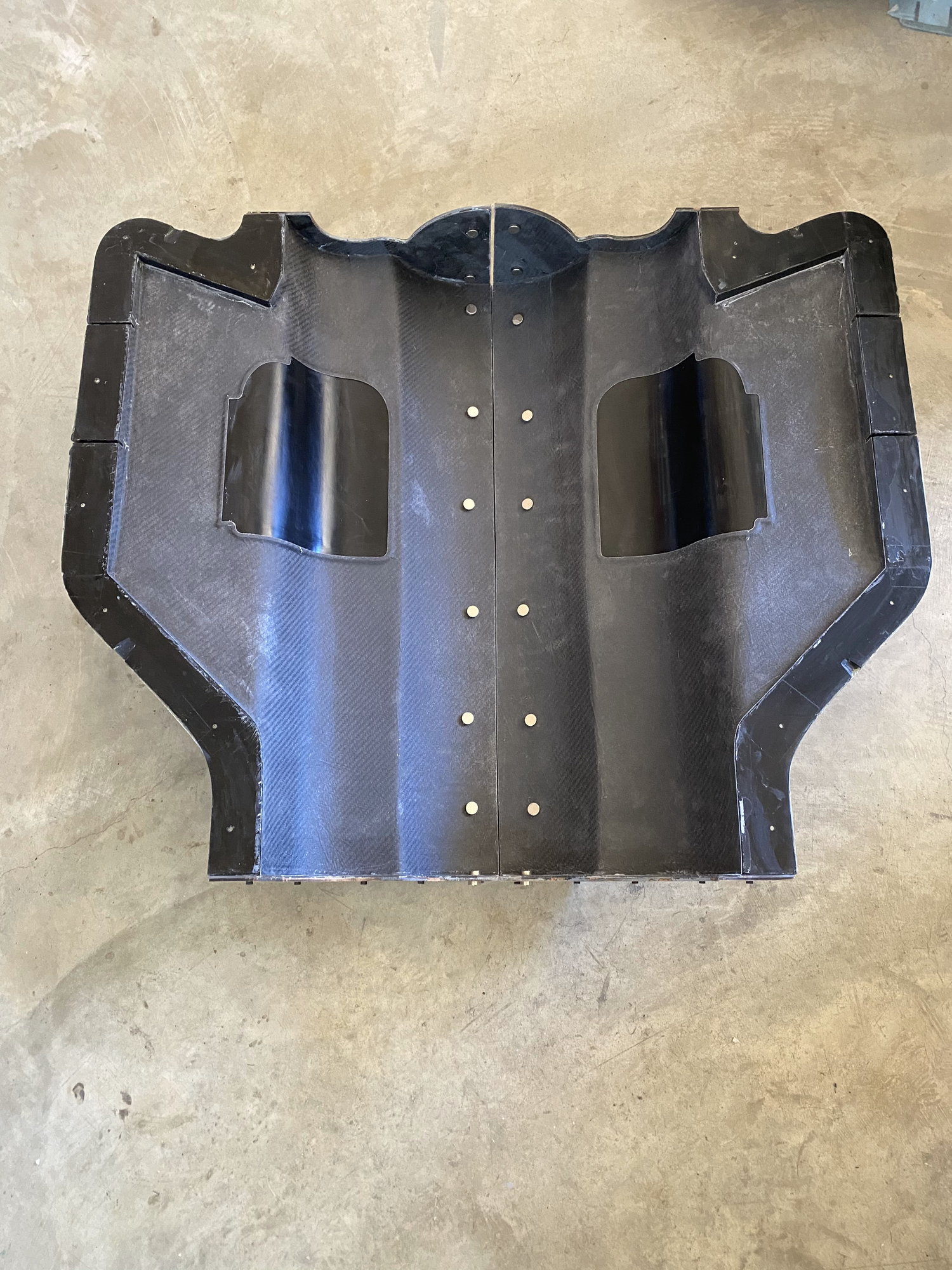
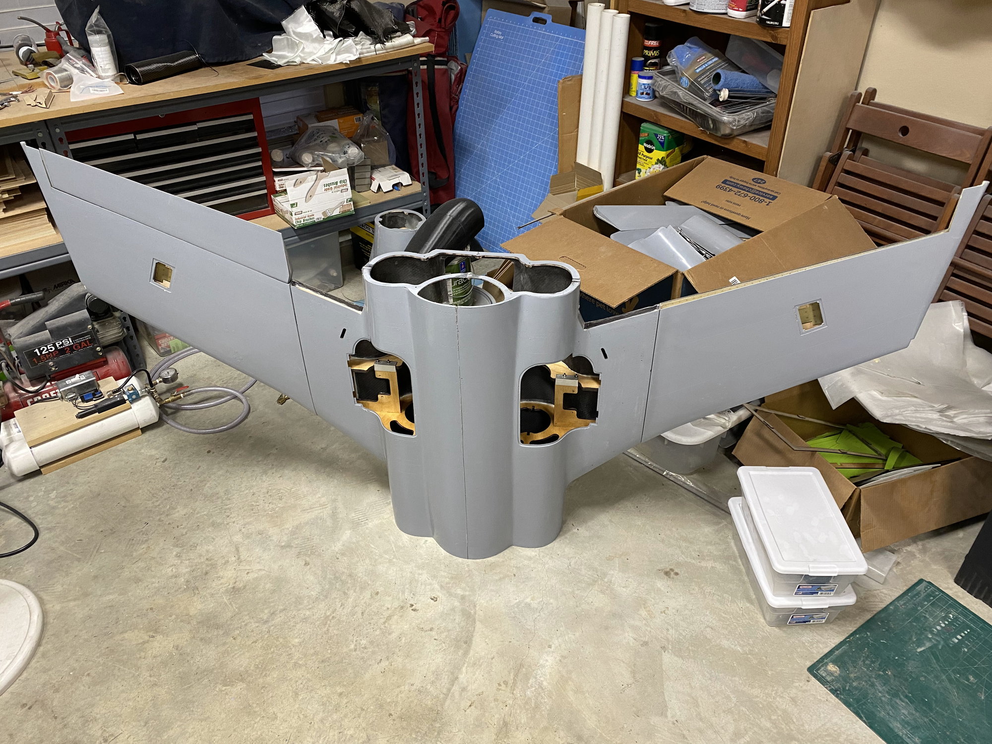
The biggest change has been with the molding process. I spent some time plus a few trial parts trying to optimize my layup, and I finally settled on using 2x layers of 3oz + 1 layer of 6oz glass cloth for the glass parts, and not using the initial surface veil. For the center and rear fuselage sections, as these take most of the flight loads, the 6oz glass was replaced by 6oz carbon cloth, sandwiched between 3oz glass. For the foam skins, the foam was sandwiched between 2 layers of 1.5oz glass.
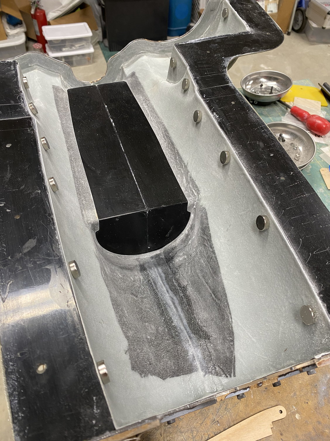
I picked a new trick, of using powerful magnets to hold the parts in the mold so that sit correctly while joining the various skins.
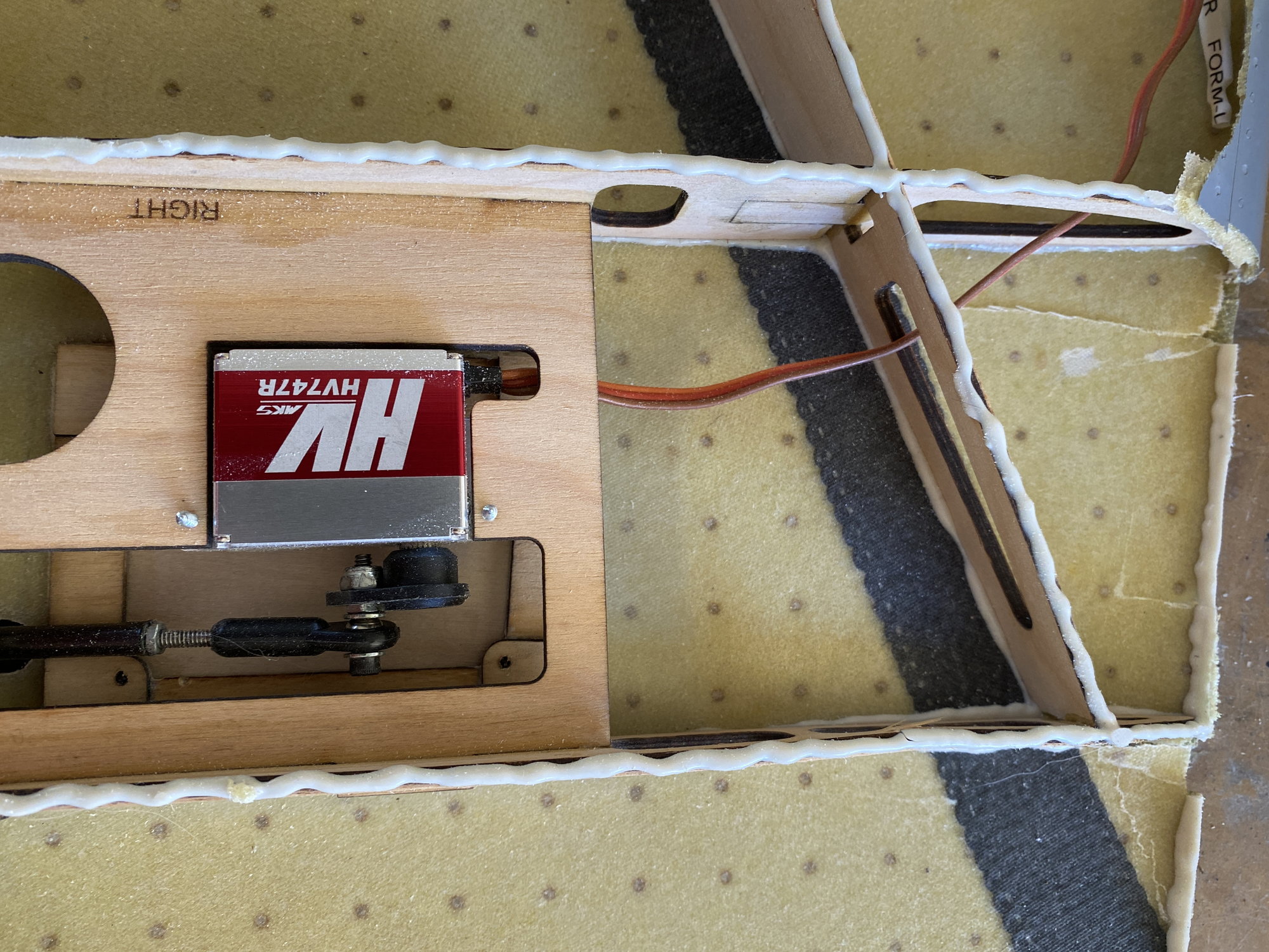
As the most probable cause of the loss of the first one was elevator servo failure or elevator servo current limiting in the Jeti CB400, the radio system was changed. The CB400 was removed and replaced with a Jeti CB210, which does not contain any current limiting poly fuses. A MKS 3850 servo replaced the MKS 777, with over 700oz-in of torque, a 50% increase. The servo mounting was also rotated 90deg to provide a more stable orientation.
The custom main gear survived the crash with just a bent pivot pin to replace, along with replacing the Electron retract motors.
Both Merlin 100 motors were able to be rebuilt under the excellent Jets Munts repair scheme.
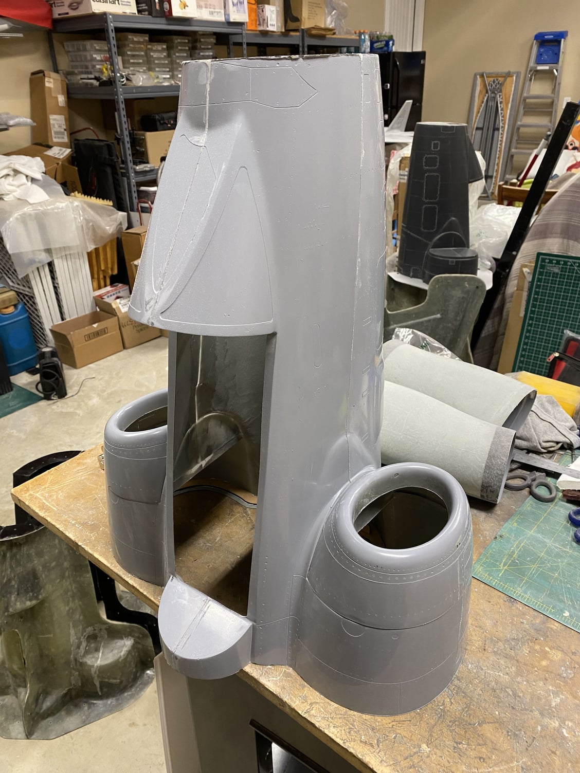
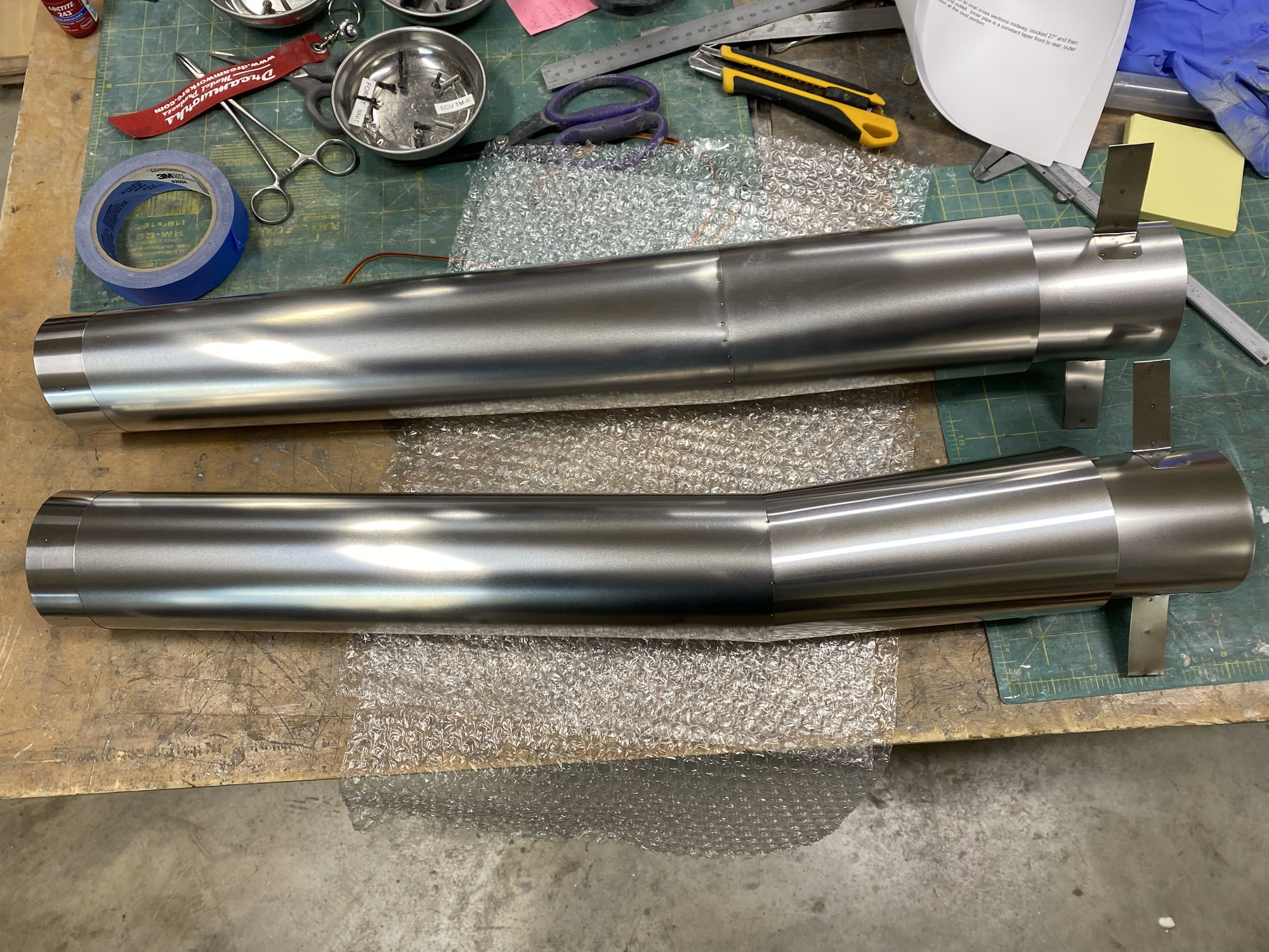
New pipes made by Garry Mueller at Jet-Tech were the final parts to install. Again thee pipes were a work of art with excellent craftsmanship.
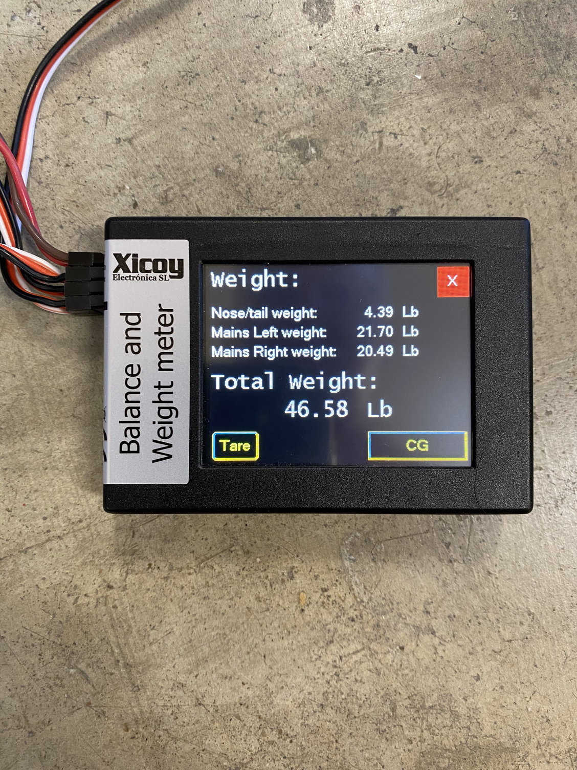
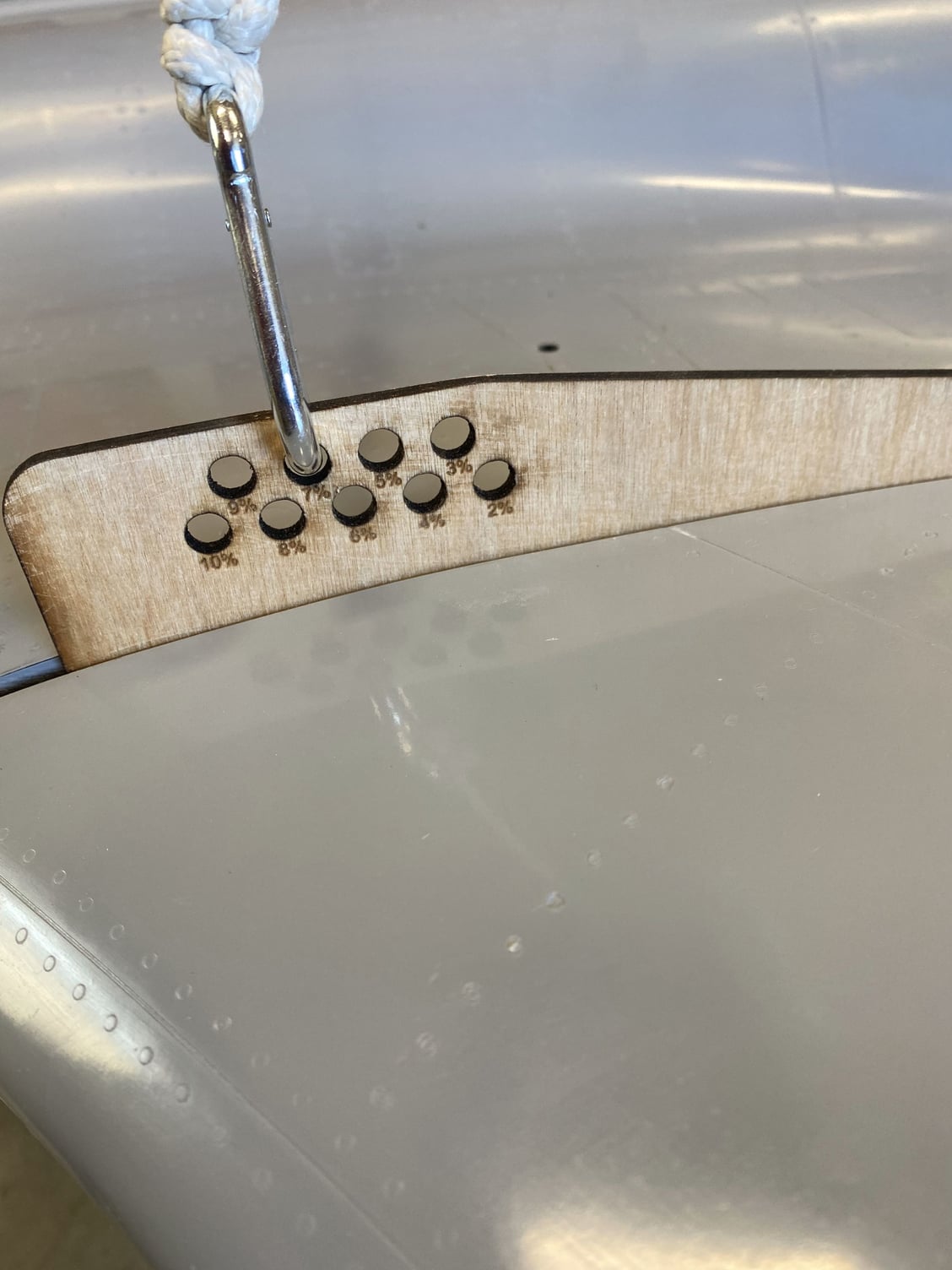
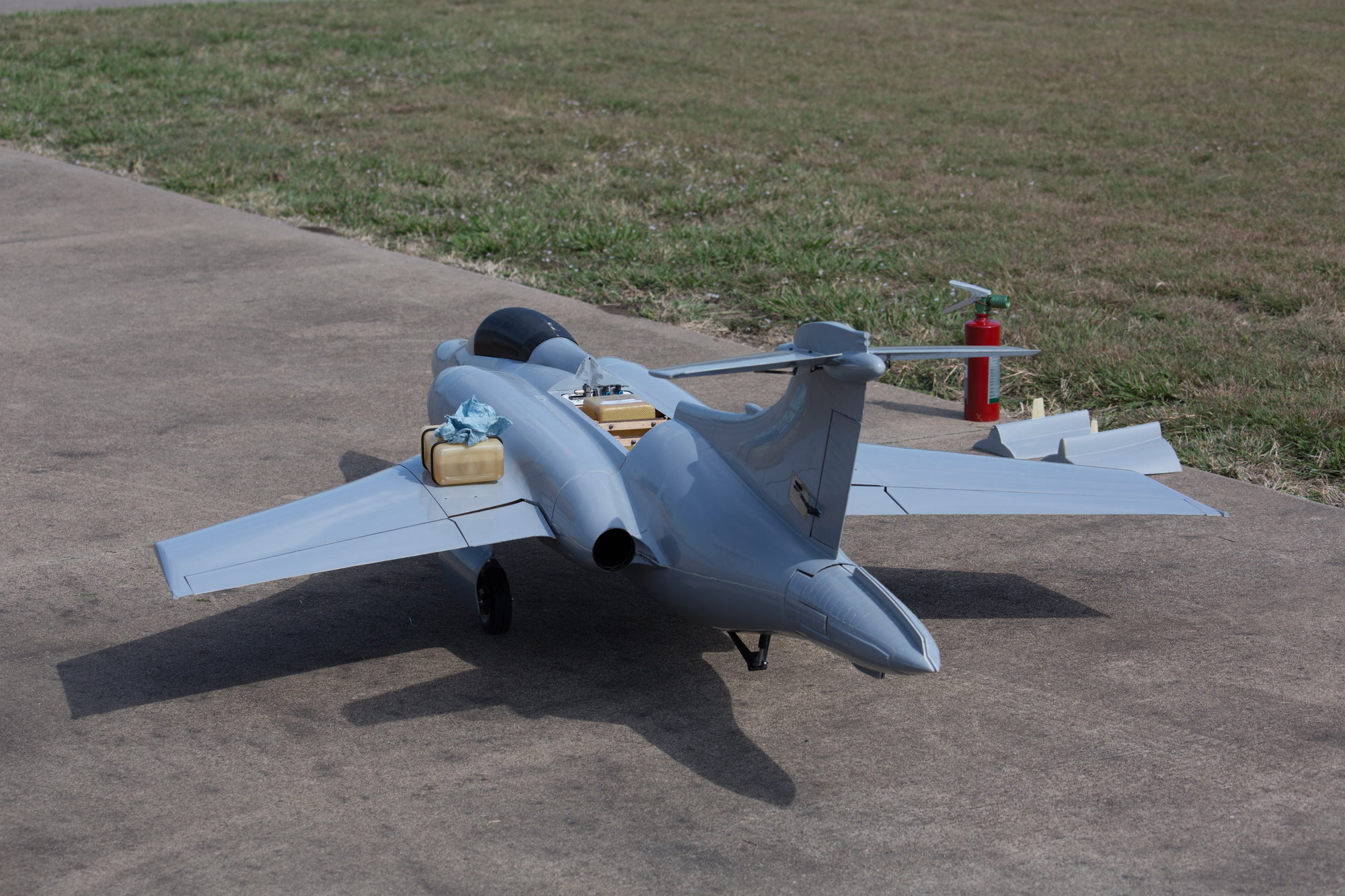
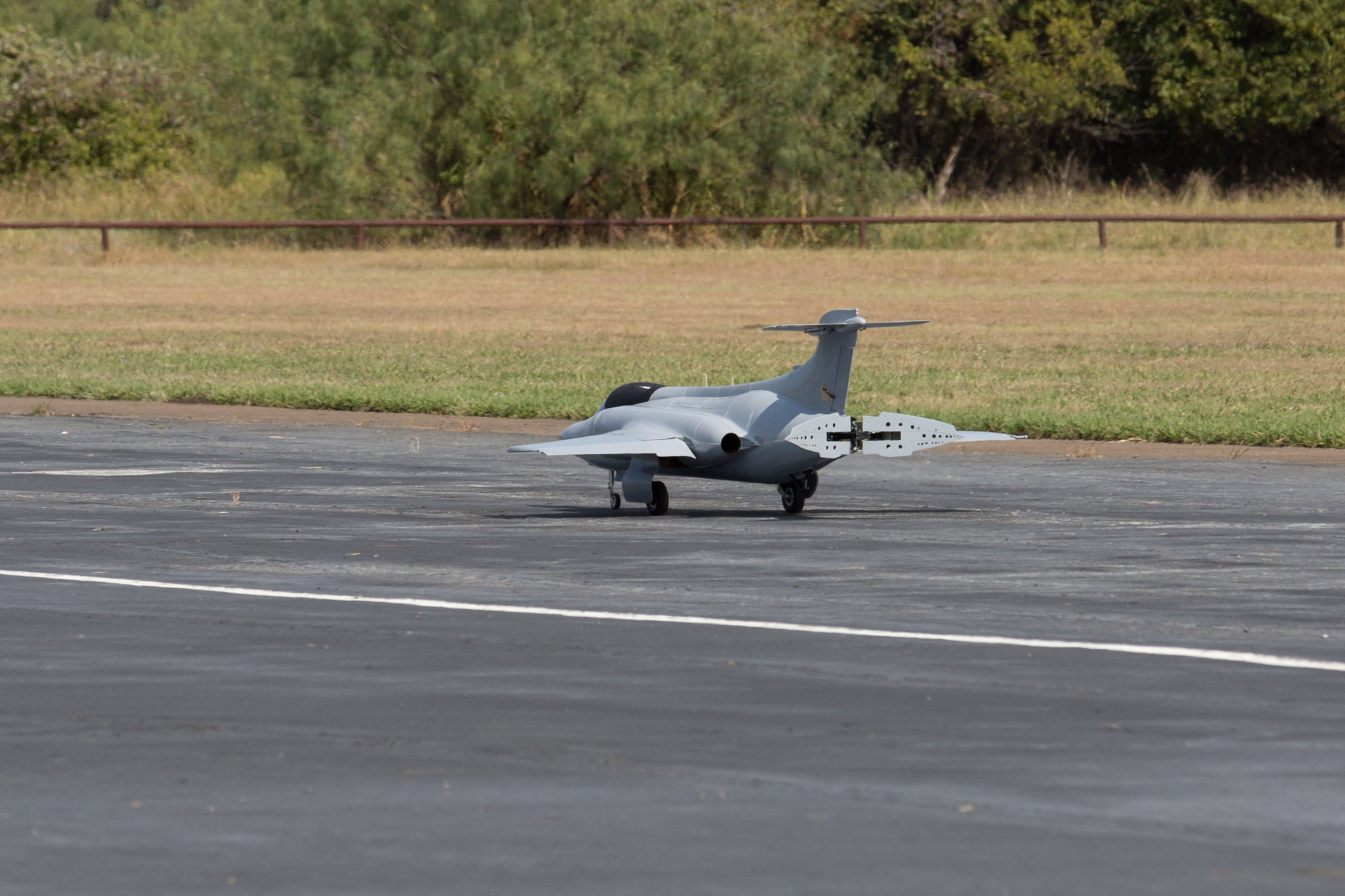
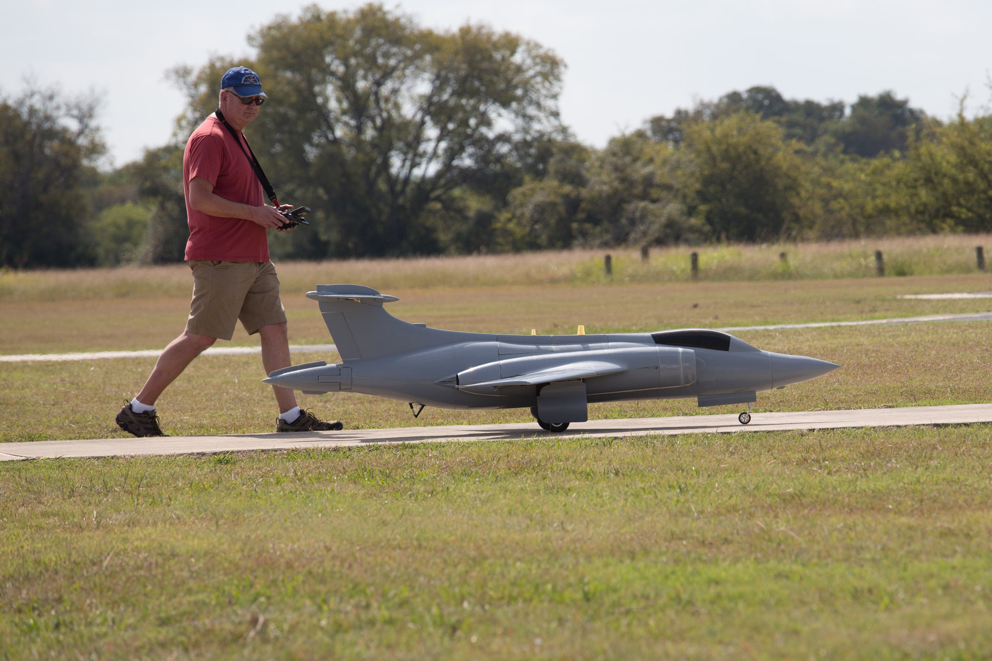
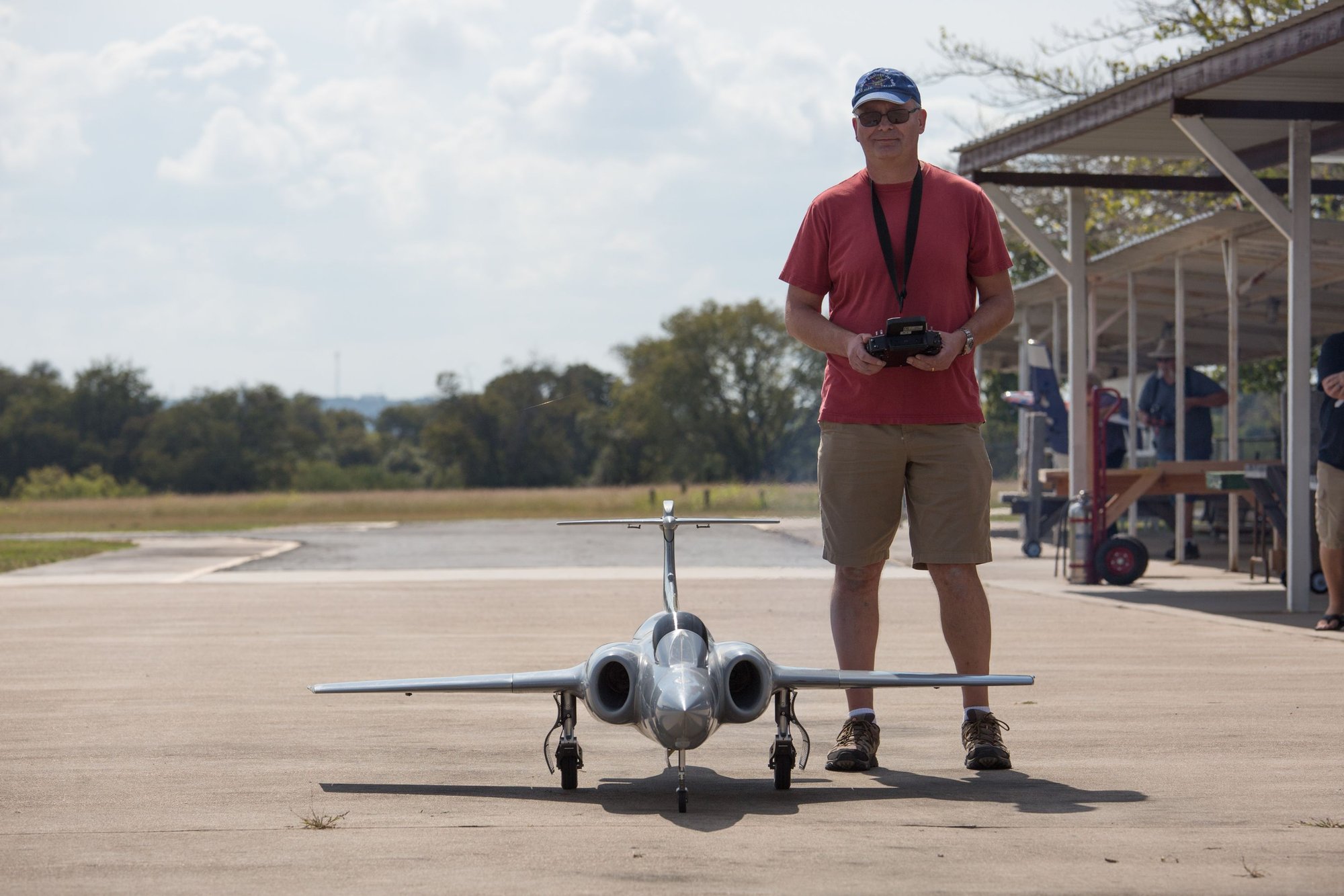
Final weight and balance showed that all the changes appear to have been beneficial, because model #2 is 5.5lb lighter than the first one, with a dry weight of 46.5lb. It balanced at 7%mac, just slightly forward of the first model without the need to add any ballast. To confirm the Xicoy balance numbers, I made a couple of hangars that fitted around the wing joiners in order to do a simple suspension test. Both methods agreed exactly.
Engine runs and taxi tests were performed yesterday with no issues noted. The fuel system was drained and checked against the Xicoy ECU telemetry figures which allowed the pump factor to be adjusted head of first flight.
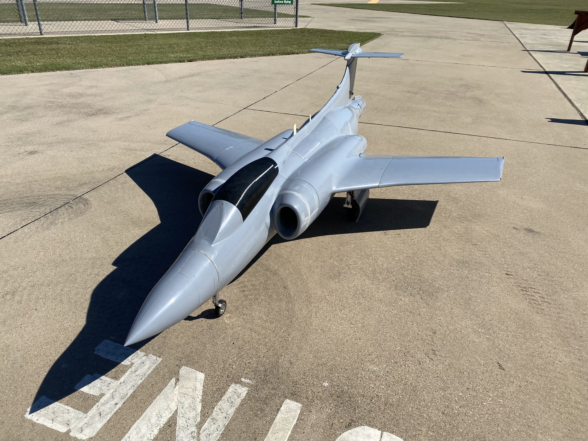
Getting close, with just a few last things to tidy up before re-attempting first flight.
The build of #2 hasn�t looked a lot different that all the previous build pictures, but it is been changed significantly internally. The majority of the internal structure has been re-designed, nothing drastic, but incorporating lessons learned from the first one plus correcting design errors spotted since it was first drawn. For the tailplane and flaperons, I switched to using glass/ foam skins rather than just glass skins, so new structure had to be designed to accommodate the thicker skins.
New molds were made for the flaperons, correcting the previous raised rivets to now flush rivets.
The biggest change has been with the molding process. I spent some time plus a few trial parts trying to optimize my layup, and I finally settled on using 2x layers of 3oz + 1 layer of 6oz glass cloth for the glass parts, and not using the initial surface veil. For the center and rear fuselage sections, as these take most of the flight loads, the 6oz glass was replaced by 6oz carbon cloth, sandwiched between 3oz glass. For the foam skins, the foam was sandwiched between 2 layers of 1.5oz glass.
I picked a new trick, of using powerful magnets to hold the parts in the mold so that sit correctly while joining the various skins.
As the most probable cause of the loss of the first one was elevator servo failure or elevator servo current limiting in the Jeti CB400, the radio system was changed. The CB400 was removed and replaced with a Jeti CB210, which does not contain any current limiting poly fuses. A MKS 3850 servo replaced the MKS 777, with over 700oz-in of torque, a 50% increase. The servo mounting was also rotated 90deg to provide a more stable orientation.
The custom main gear survived the crash with just a bent pivot pin to replace, along with replacing the Electron retract motors.
Both Merlin 100 motors were able to be rebuilt under the excellent Jets Munts repair scheme.
New pipes made by Garry Mueller at Jet-Tech were the final parts to install. Again thee pipes were a work of art with excellent craftsmanship.
Final weight and balance showed that all the changes appear to have been beneficial, because model #2 is 5.5lb lighter than the first one, with a dry weight of 46.5lb. It balanced at 7%mac, just slightly forward of the first model without the need to add any ballast. To confirm the Xicoy balance numbers, I made a couple of hangars that fitted around the wing joiners in order to do a simple suspension test. Both methods agreed exactly.
Engine runs and taxi tests were performed yesterday with no issues noted. The fuel system was drained and checked against the Xicoy ECU telemetry figures which allowed the pump factor to be adjusted head of first flight.
Getting close, with just a few last things to tidy up before re-attempting first flight.
The following users liked this post:
grbaker (10-18-2021)

The following users liked this post:
grbaker (10-18-2021)

The following users liked this post:
grbaker (10-18-2021)
10-17-2021, 01:29 PM
#658
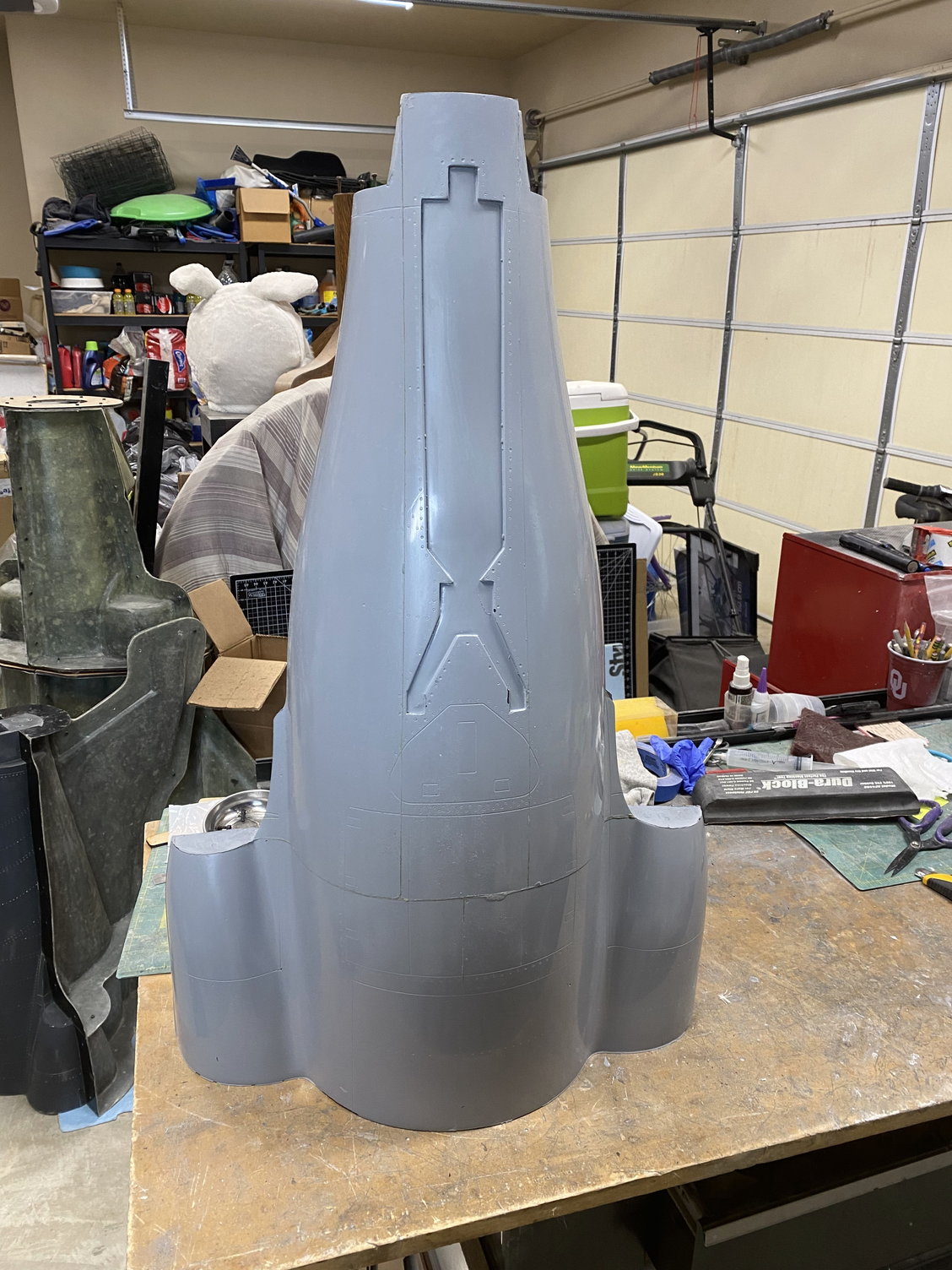
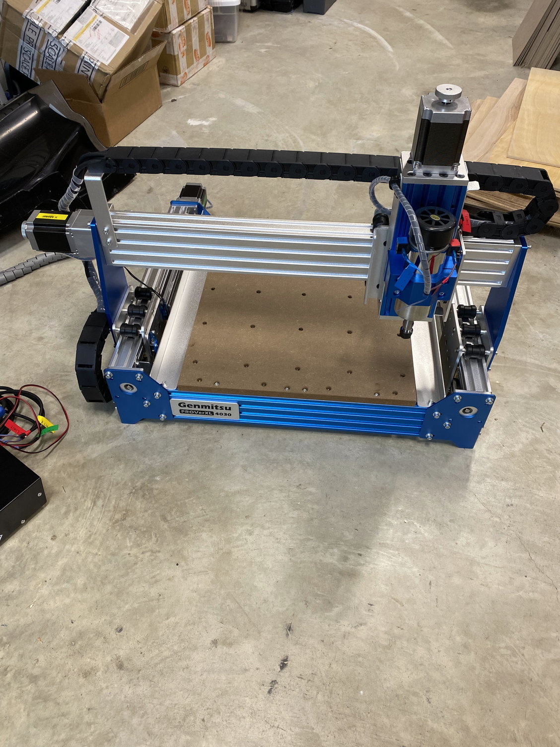
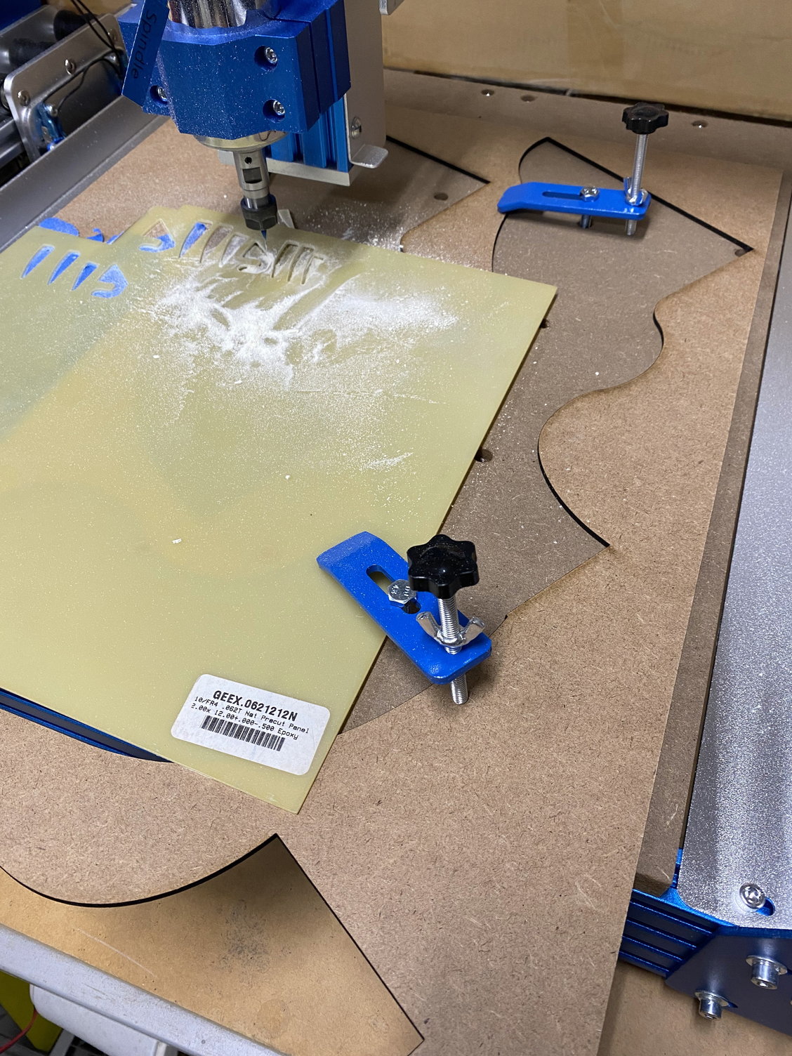
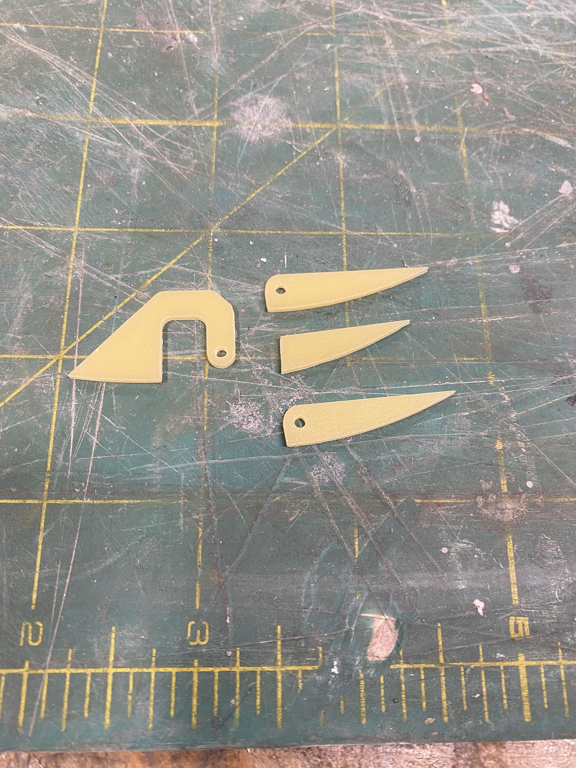
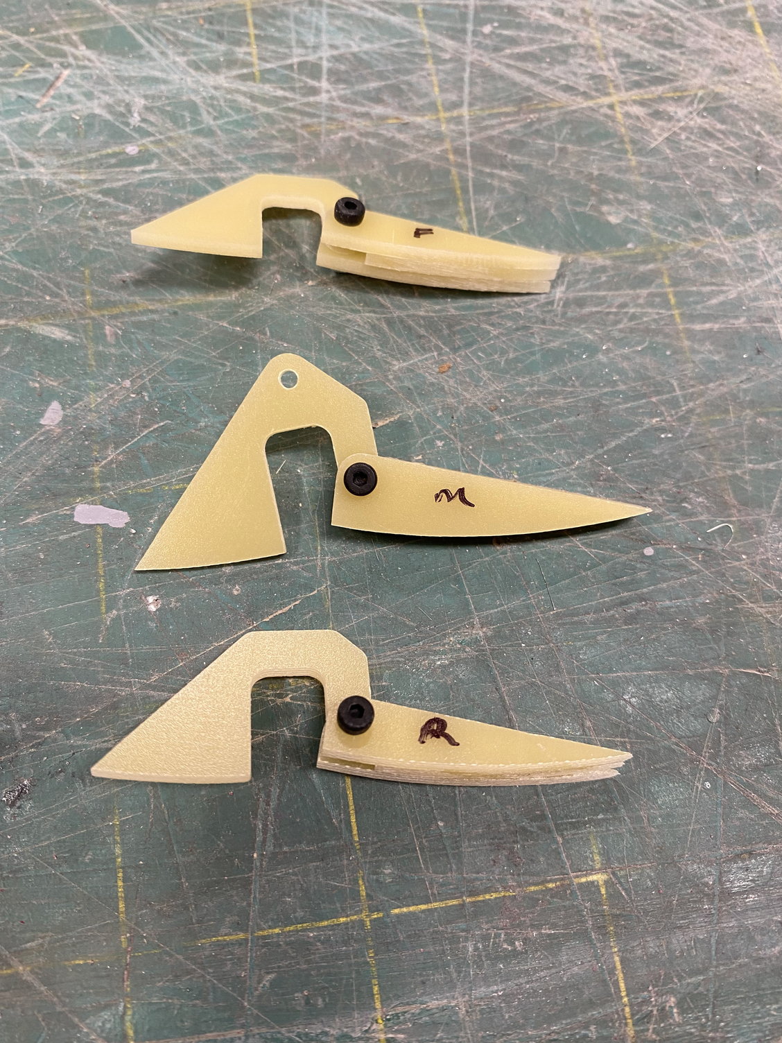
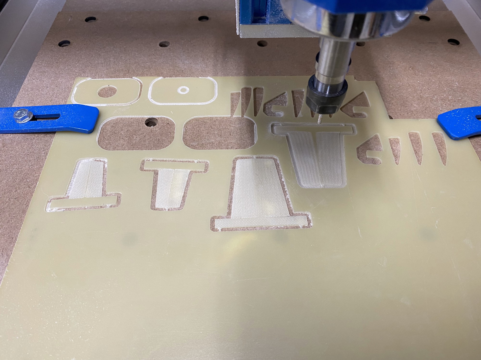
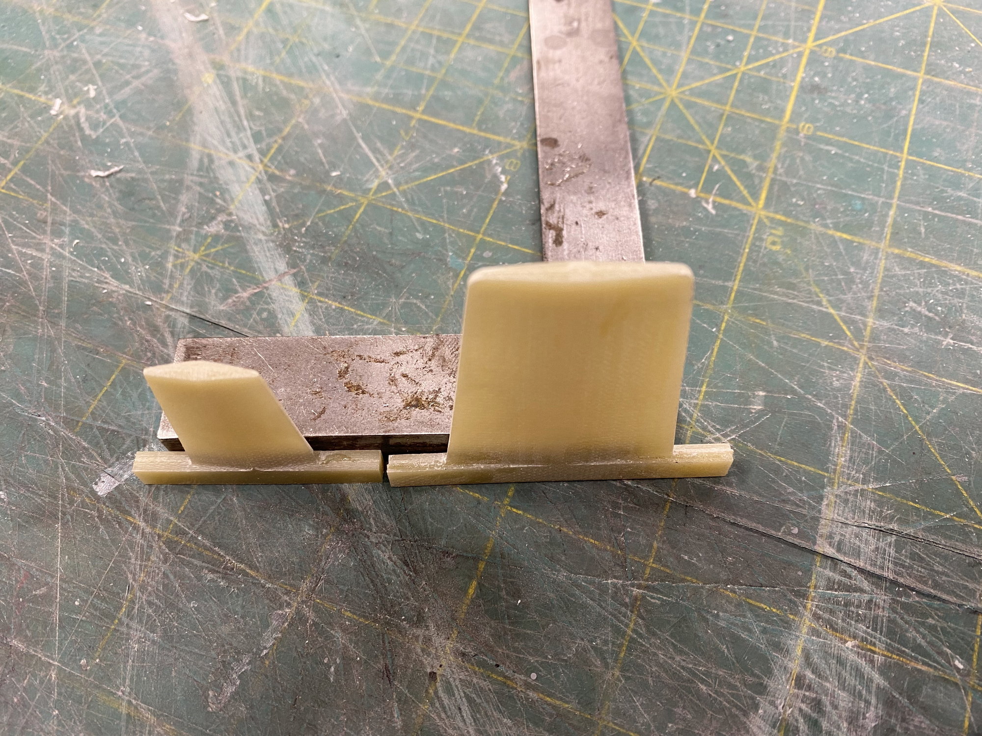
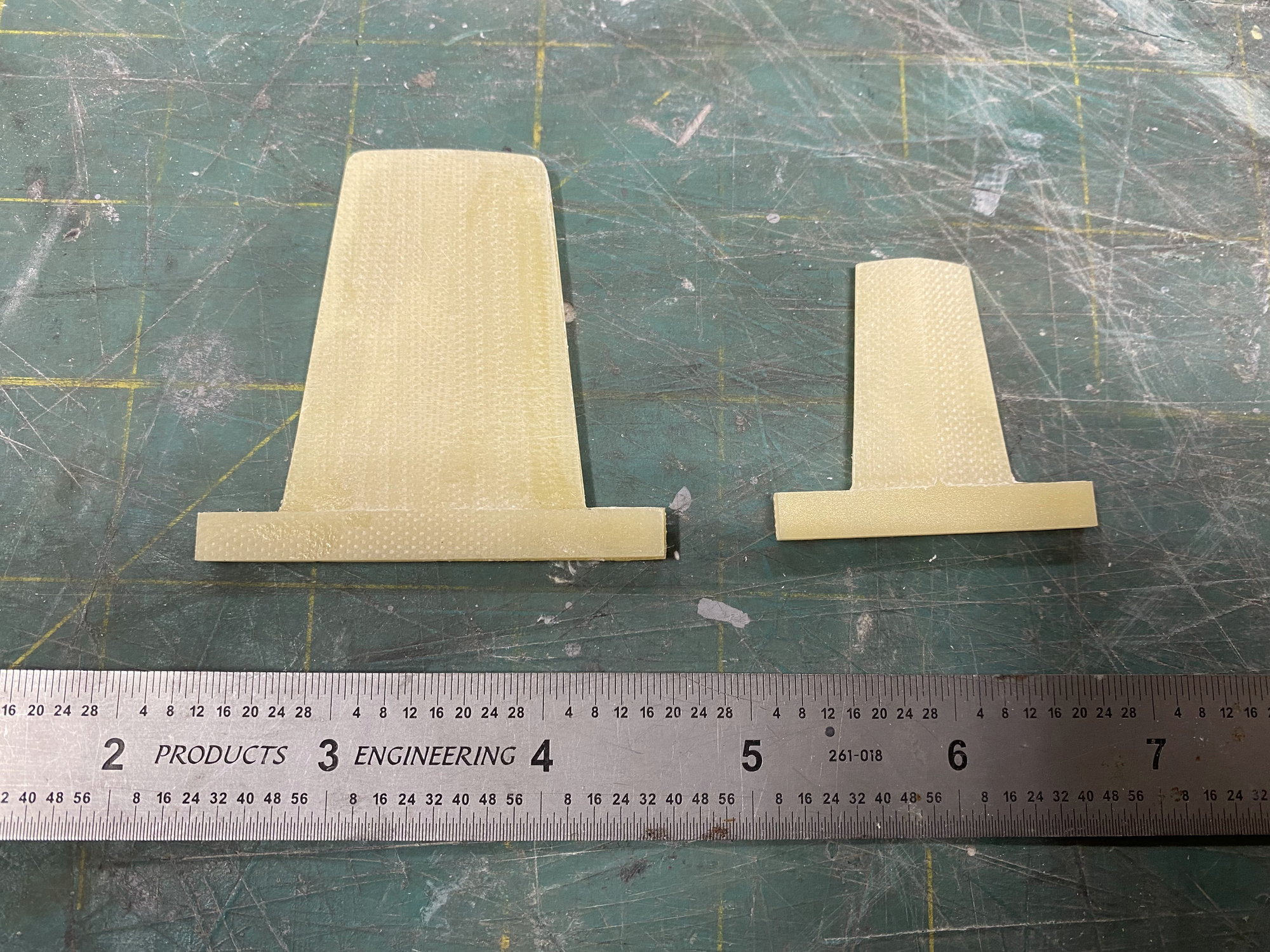
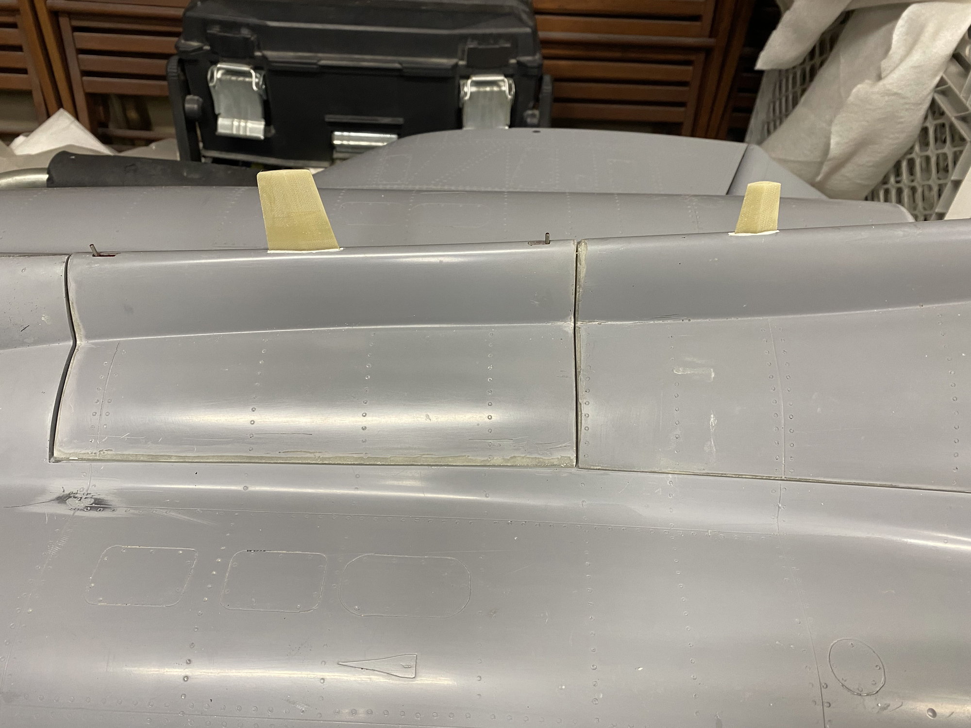
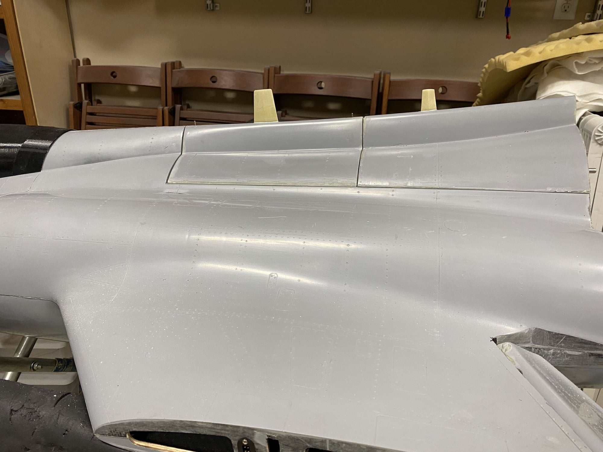
As I was teaching myself about the CNC router, I also made the two very prominent antenna that sit on the dorsal spine.These have a diamond profile, so left and right halved were made and glued together. As a trial, these worked out very well.
The following 2 users liked this post by JSF-TC:
grbaker (10-18-2021),
jcterrettaz (10-21-2021)
The following users liked this post:
grbaker (10-18-2021)


The following users liked this post:
jetflyr (10-18-2021)
10-17-2021, 09:02 PM
#664

Looks great with a significant weight saving 👍
Have you done a simple suspension test to see how bad the lateral in balance really is.1.5lb at the main wheels is significant.
Dave
Have you done a simple suspension test to see how bad the lateral in balance really is.1.5lb at the main wheels is significant.
Dave

 10-18-2021, 08:48 AM
#666
Tom,
I think you are asking about the horizontal stab flaps.
On reflection after the loss of the first model, I think the tailplane pitching moment caused by the deflection of the tailplane flaps may have contributed to the extra current draw and possible servo failure.
On this one, I have de-coupled the tailplane flaps from the flap/ flaperon mixing flight modes, and I have them on a separate slider. For initial flights I will keep them retracted. Once I am comfortable with the model I will investigate how much extra current draw they cause when I deflect them before deciding how to mix them back in with the flaps/ flaperons.
Paul
 10-21-2021, 05:59 PM
#669
So, good news and bad.
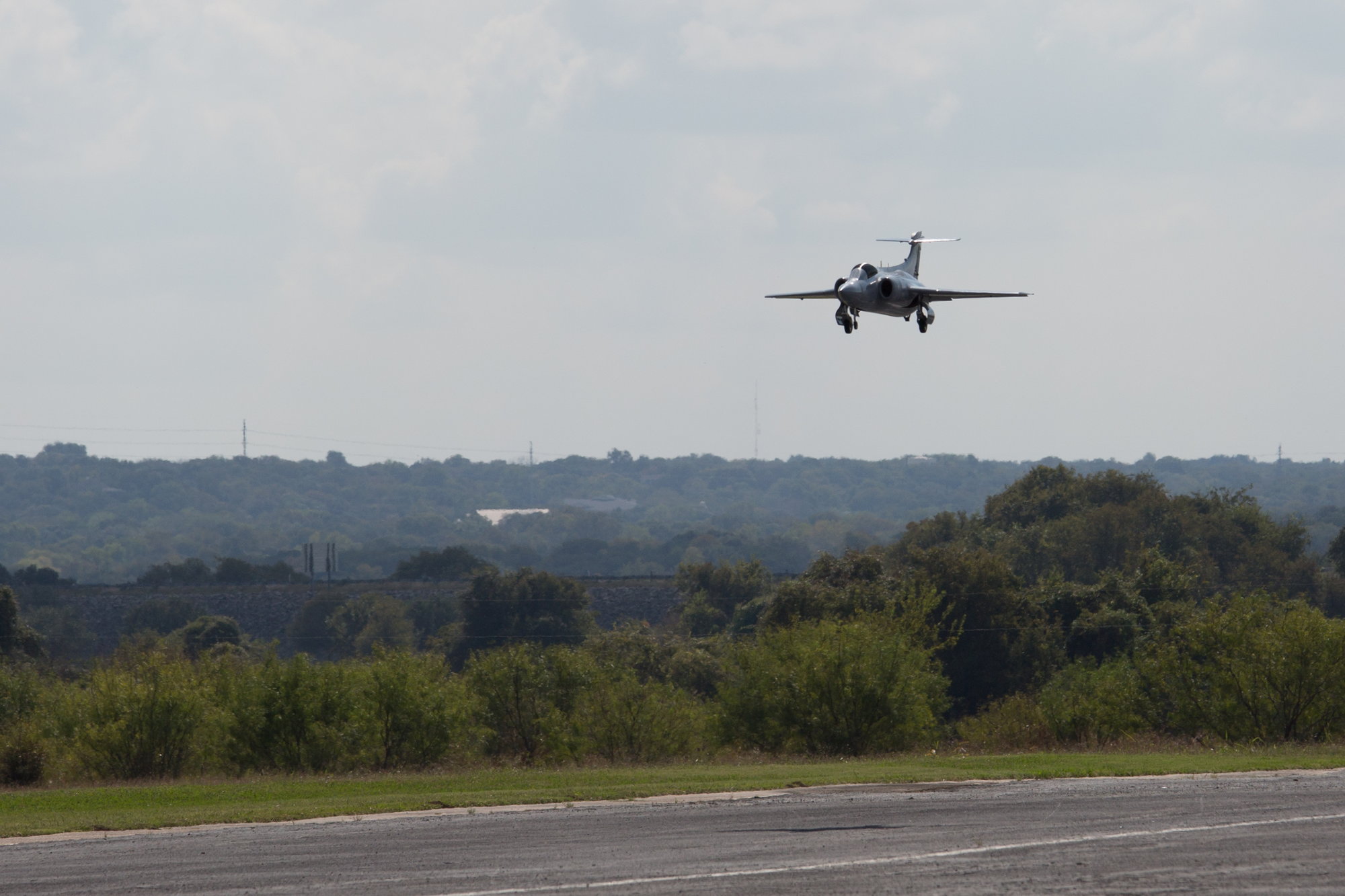
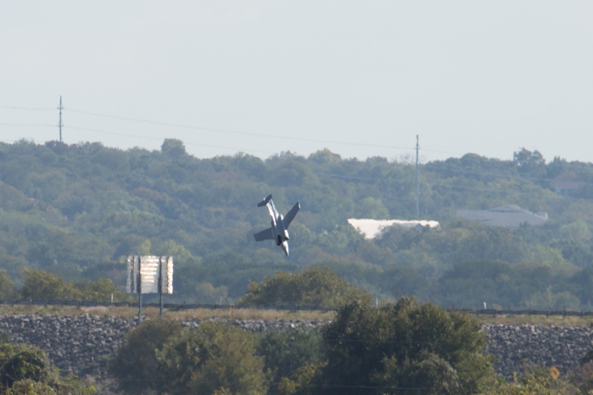
Achieved a successful first flight today, however the model was lost on the second flight.
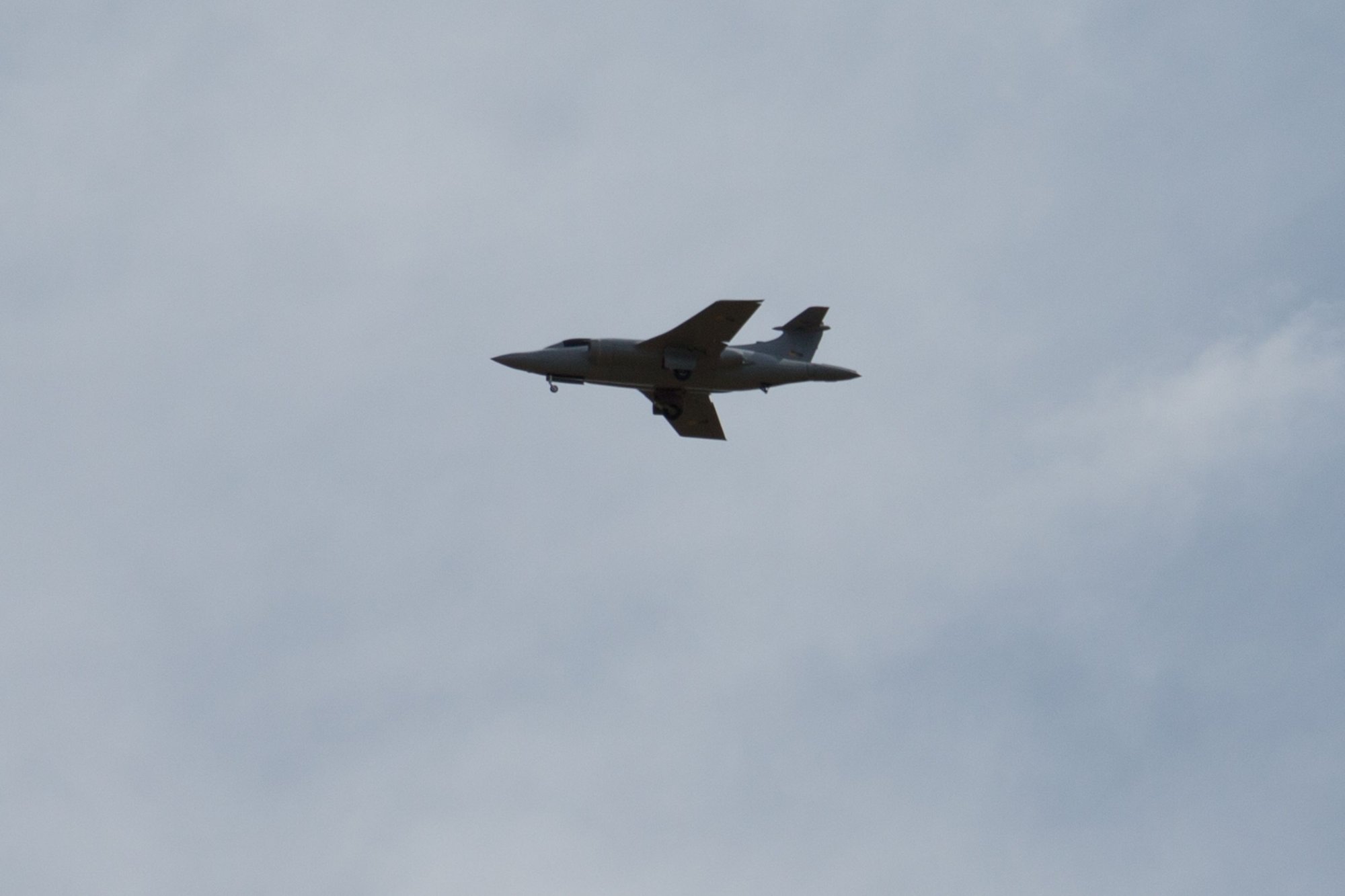
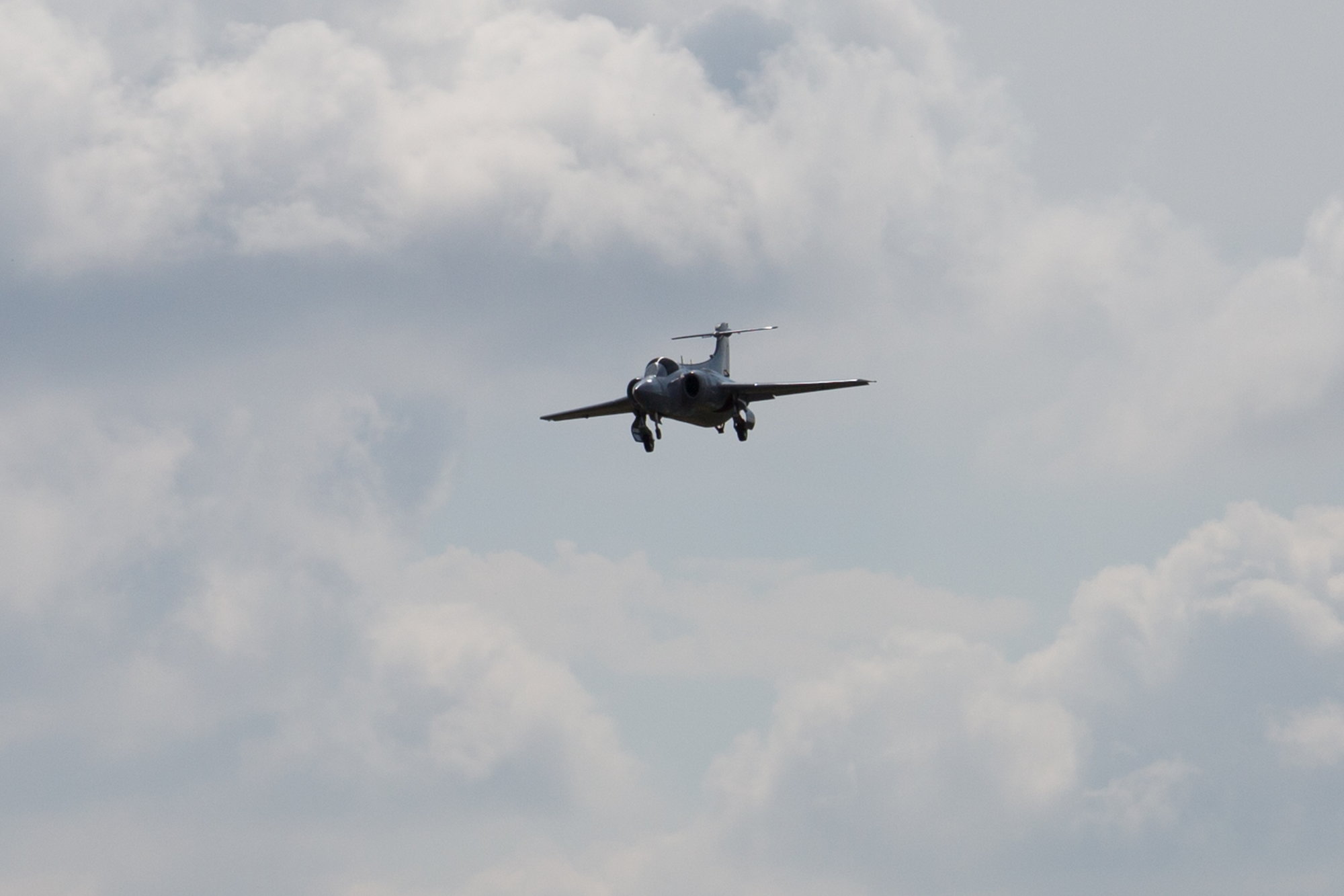
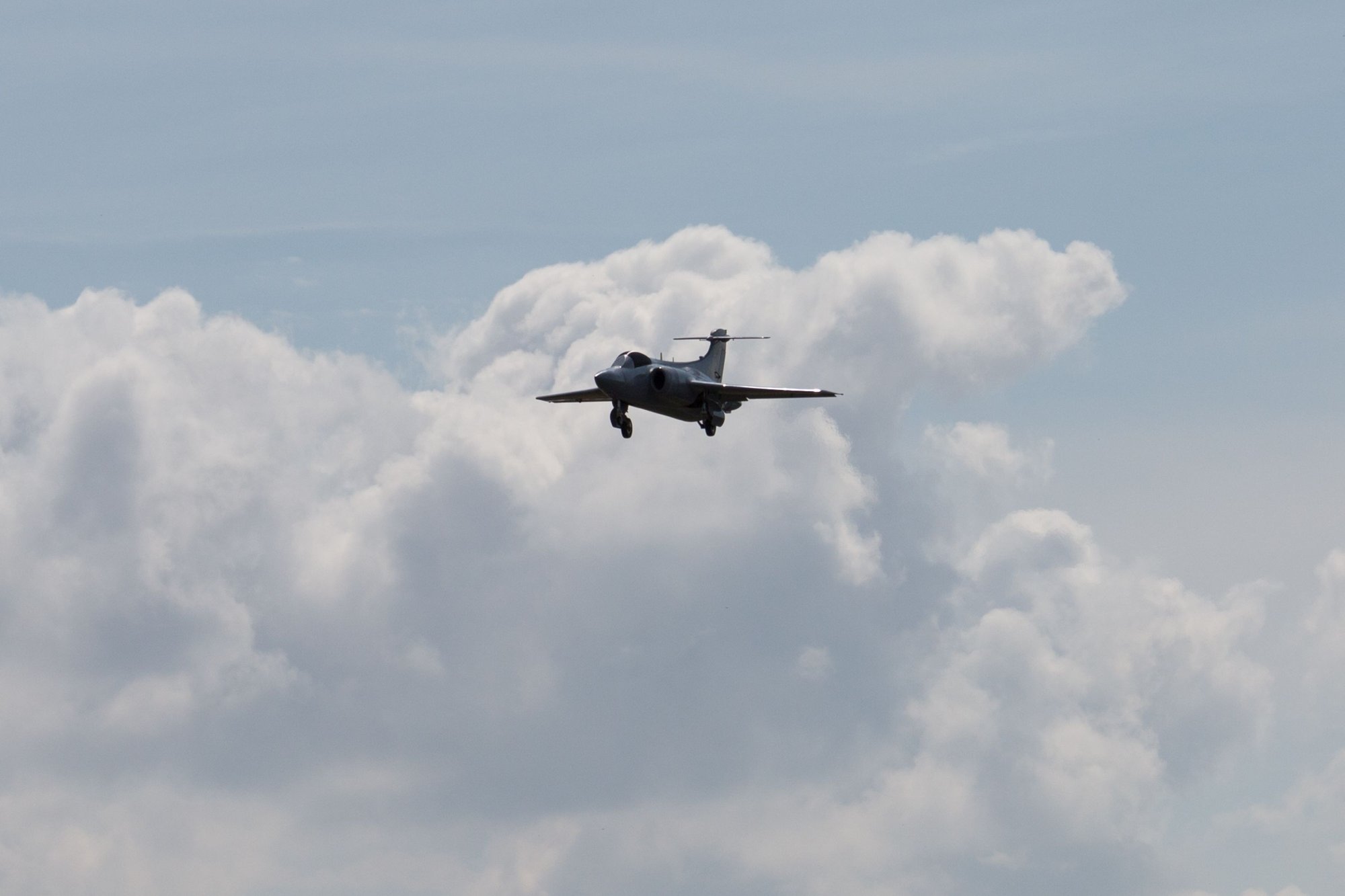
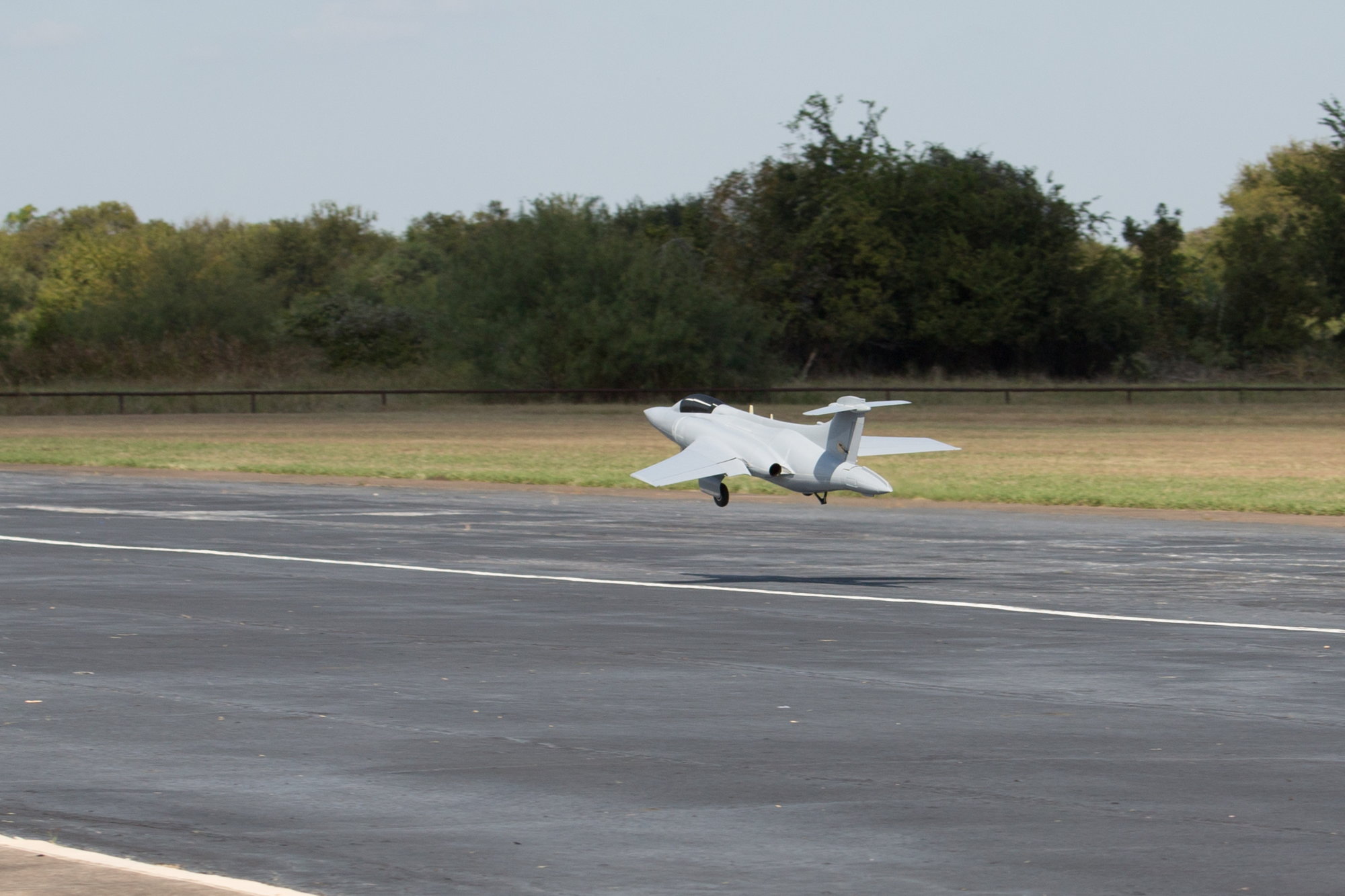
Conditions were perfect, with a light N/NE wind at around 5kn with pleasant temperatures. I was super anxious given what had happened with model #1, but with support from Ron, Buck, Stephen and Dawn I finally was ready to try again.
The first take off was little rough as I allowed the model to drift towards the left side of the runway and had to haul it off just before it ran off the edge. It was not helped by being significantly out of trim in pitch (nose down) and roll (left), so there were a few anxious seconds before I managed to get it climbing away. Throttling back to hold a sensible gear down speed, I worked to get it trimmed using the Jeti auto-trim feature, followed by some manual fine-tuning. My biggest observation was that roll control was very sensitive and ratchety, it was hard to control smoothly without sudden large roll movements. Bringing in the gyro helped some, but it was still hard work to control smoothly.
As per the plan, I left the gear down for the first flight and concentrated on feeling out the model in preparation for landing. I flew about 5 laps around the pattern getting comfortable with it, and then flew a few practice approaches and overshoots before committing to a landing. I decided to fly the entire flight with take off flap (inner flaps and flaperons deflected). The flare and touchdown felt predictable with a fairly gentle touchdown and no bounce, if a little fast. I deployed the speedbrake once on the ground and applied full brake. Roll out was a little squirrely but I got it stopped on the runway with no scratches or damage. That counts as success in my book.
The biggest take-away was the sensitive and ratchety roll control. We decided to remove the flaperon droop with take-off flap selected and reduce the landing flap droop to the amount we flew at take-off flap on flight 1. The thought was that the drooped flaperons and large open gear doors were degrading the roll control, and that it would get better once cleaned up. It also needed a lot of nose-up trim, but that is probably attributable to the more forward c.g. than the first model.


Achieved a successful first flight today, however the model was lost on the second flight.
Conditions were perfect, with a light N/NE wind at around 5kn with pleasant temperatures. I was super anxious given what had happened with model #1, but with support from Ron, Buck, Stephen and Dawn I finally was ready to try again.
The first take off was little rough as I allowed the model to drift towards the left side of the runway and had to haul it off just before it ran off the edge. It was not helped by being significantly out of trim in pitch (nose down) and roll (left), so there were a few anxious seconds before I managed to get it climbing away. Throttling back to hold a sensible gear down speed, I worked to get it trimmed using the Jeti auto-trim feature, followed by some manual fine-tuning. My biggest observation was that roll control was very sensitive and ratchety, it was hard to control smoothly without sudden large roll movements. Bringing in the gyro helped some, but it was still hard work to control smoothly.
As per the plan, I left the gear down for the first flight and concentrated on feeling out the model in preparation for landing. I flew about 5 laps around the pattern getting comfortable with it, and then flew a few practice approaches and overshoots before committing to a landing. I decided to fly the entire flight with take off flap (inner flaps and flaperons deflected). The flare and touchdown felt predictable with a fairly gentle touchdown and no bounce, if a little fast. I deployed the speedbrake once on the ground and applied full brake. Roll out was a little squirrely but I got it stopped on the runway with no scratches or damage. That counts as success in my book.
The biggest take-away was the sensitive and ratchety roll control. We decided to remove the flaperon droop with take-off flap selected and reduce the landing flap droop to the amount we flew at take-off flap on flight 1. The thought was that the drooped flaperons and large open gear doors were degrading the roll control, and that it would get better once cleaned up. It also needed a lot of nose-up trim, but that is probably attributable to the more forward c.g. than the first model.
Last edited by JSF-TC; 10-21-2021 at 06:02 PM.
10-21-2021, 06:20 PM
#670
With the changes made, batteries charged and the model and telemetry checked for anything abnormal we set off for flight 2.
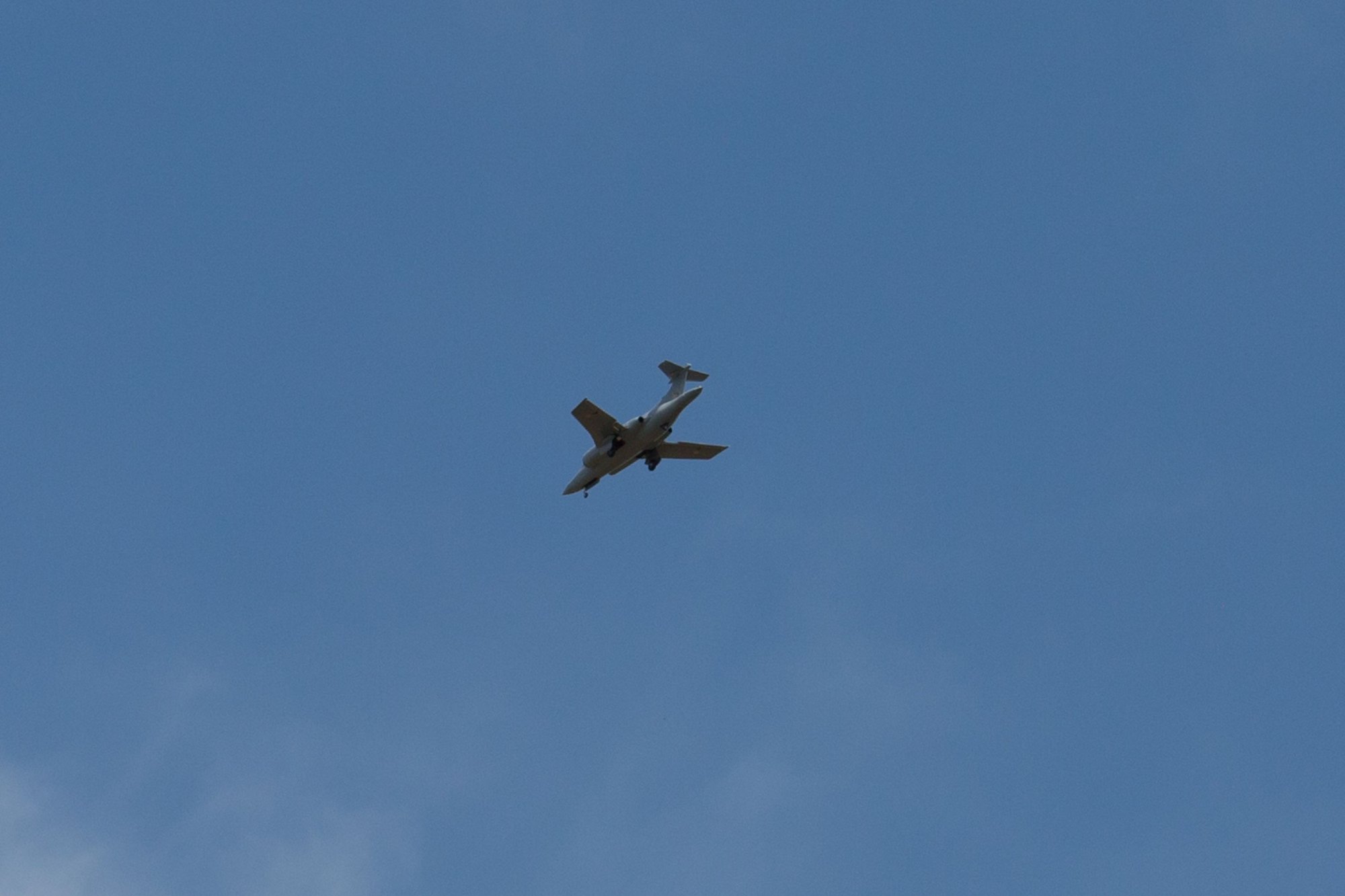
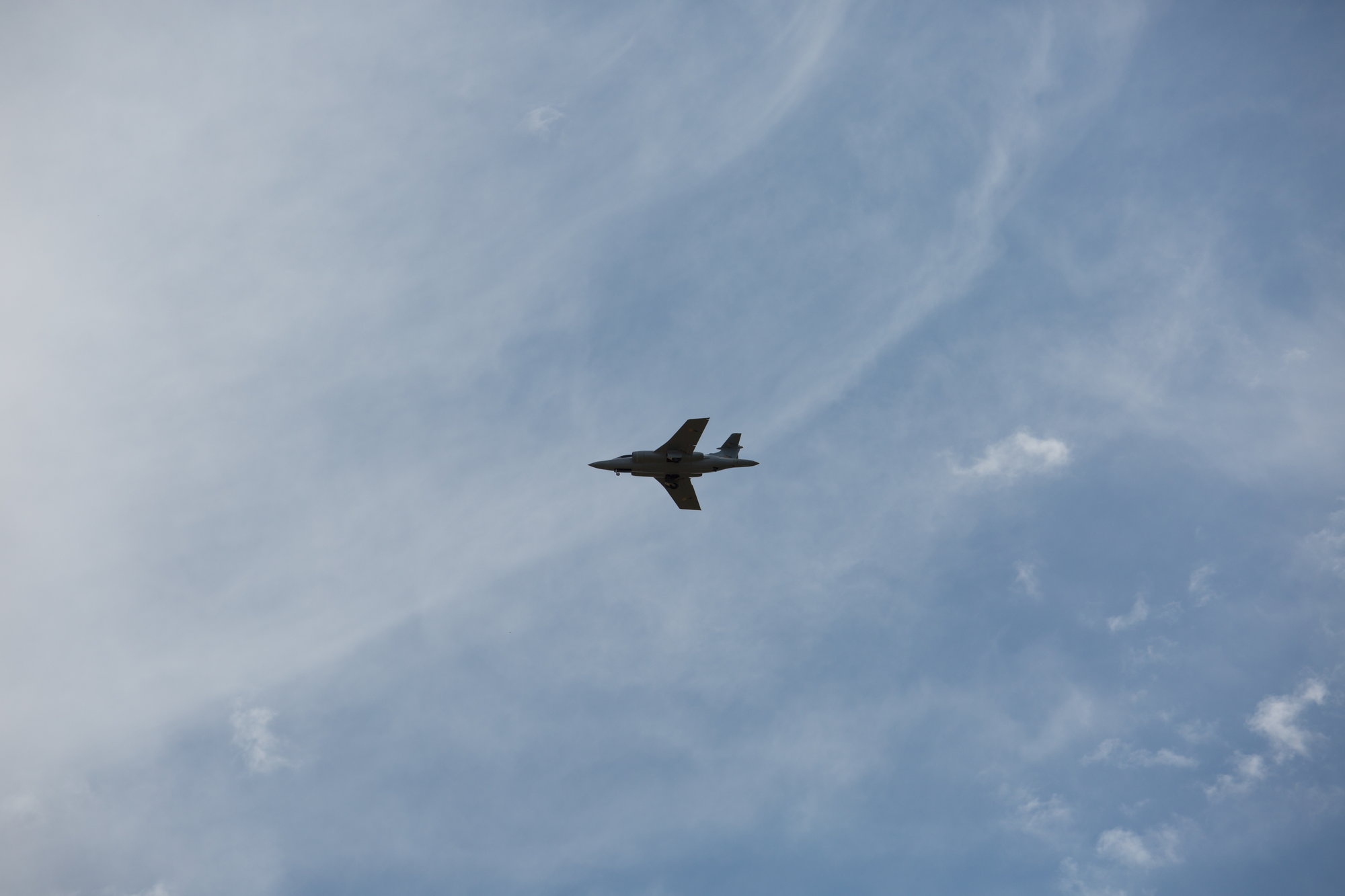
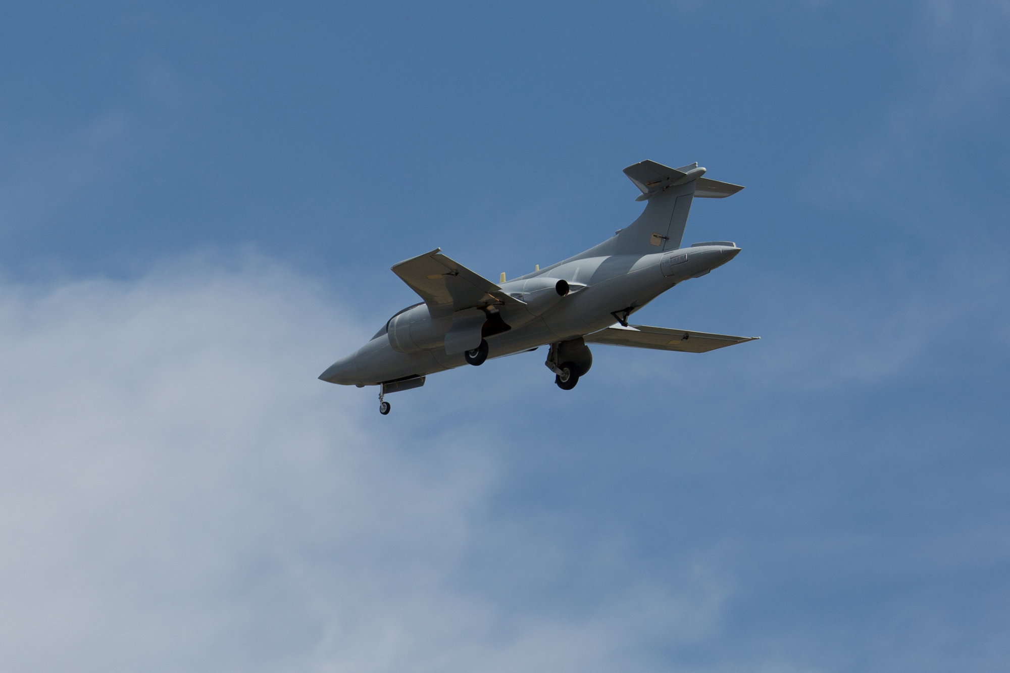
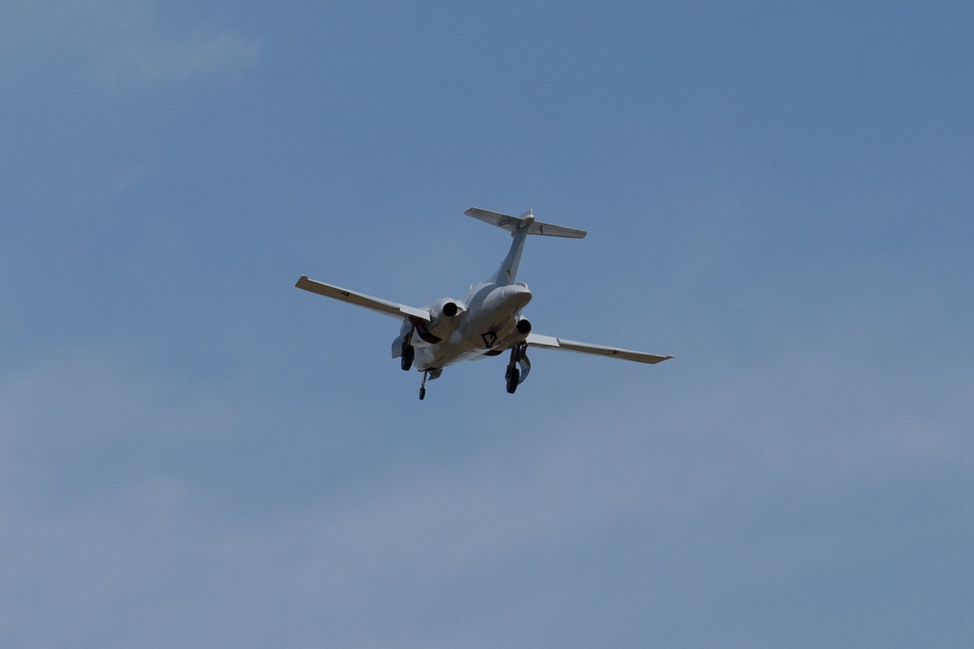
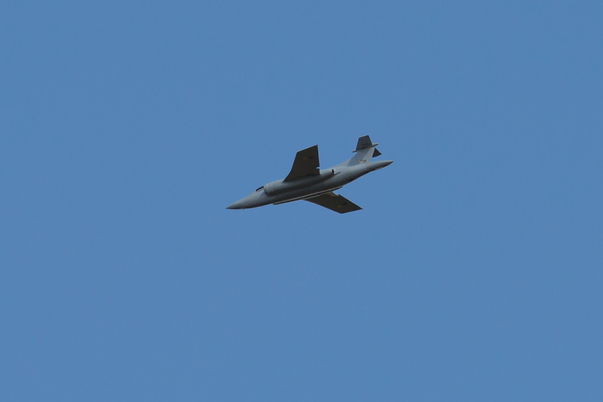
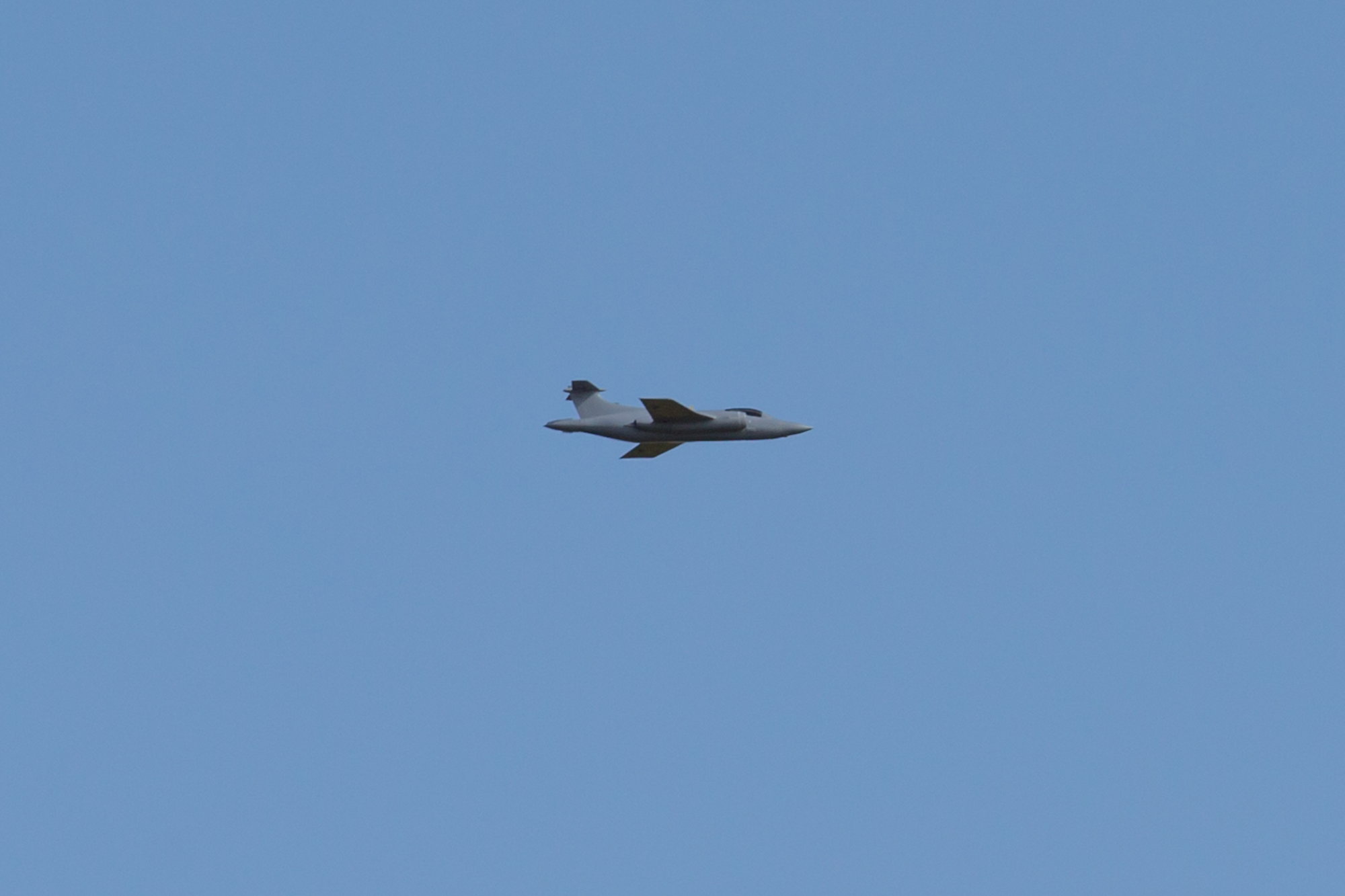
The take-off was much more relaxed, with it being in trim. It lifted off by itself just before I initiated the rotation. Climb away was smooth and positive. On downwind, the gear was retracted and the model became much smoother in roll. I flew a circuit gear up with take off flap selected and then selected flaps up on the next down wind leg. After re-trimming I initiated a right descending turn to fly back up the runway.
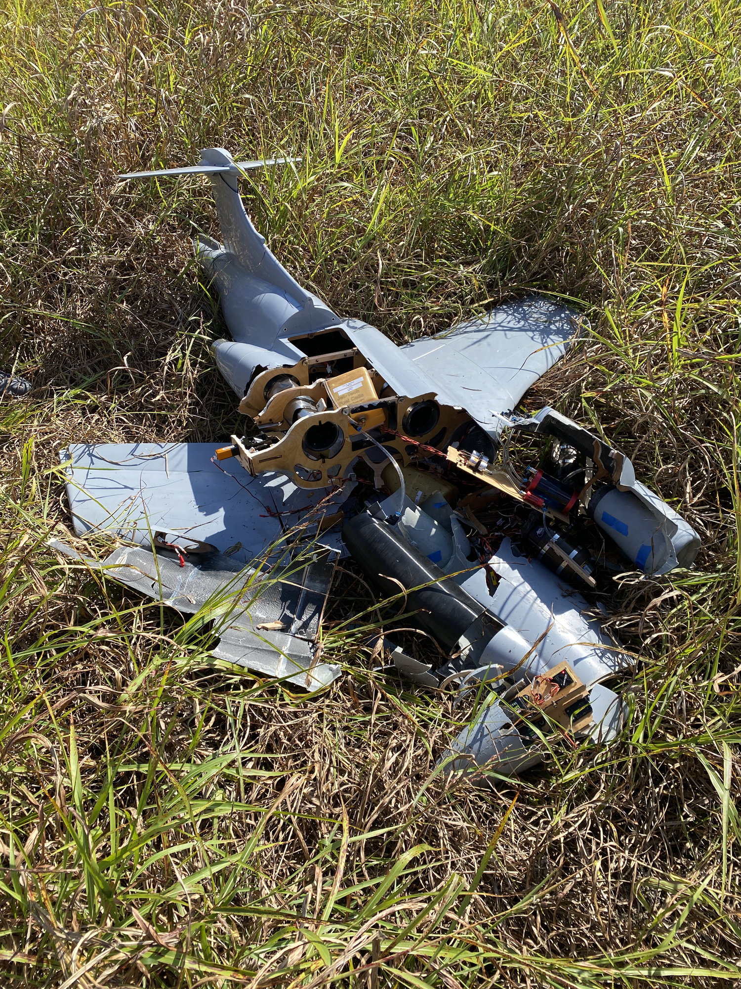
However, at about half-way around the turn, with no warning the model snaped to the right and entered an aggressive unrecoverable spin. Luckily Steven called out to kill the engines and I got them off just before it descended below the tree-line, avoiding a post-crash fire. The debris confirmed that there was no significant forward speed on impact, with all the parts contained within the planform of the model.
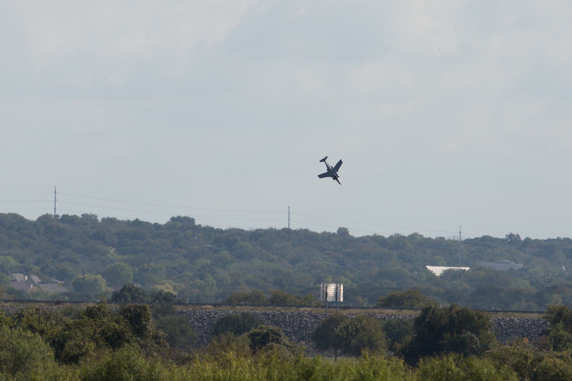
It is clearer on the iphone, but from the video, it is clear that the model snaps to the right and enters a spin - what I still cannot work out is the cause - I do not recall pulling the model in the turn, it was a gentle descending turn and GPS shows that it was doing just over 100mph, the same as the rest of the flight. Both engines were running and the throttle was unchanged since throttling back after take-off.
I know the full-scale was very unforgiving at slow speeds, so potentially the model has retained some of these traits based on its overall configuration. I incorporated 3deg of washout into the wings to avoid tip-stall. Potentially the T-tail got blanked by the fuselage, but with a forward c.g. I would have thought that even with a tailplane stall, the nose would have dropped.
Lots to reflect on before deciding what to do next with the Buccaneer project.
Paul
The take-off was much more relaxed, with it being in trim. It lifted off by itself just before I initiated the rotation. Climb away was smooth and positive. On downwind, the gear was retracted and the model became much smoother in roll. I flew a circuit gear up with take off flap selected and then selected flaps up on the next down wind leg. After re-trimming I initiated a right descending turn to fly back up the runway.
However, at about half-way around the turn, with no warning the model snaped to the right and entered an aggressive unrecoverable spin. Luckily Steven called out to kill the engines and I got them off just before it descended below the tree-line, avoiding a post-crash fire. The debris confirmed that there was no significant forward speed on impact, with all the parts contained within the planform of the model.
It is clearer on the iphone, but from the video, it is clear that the model snaps to the right and enters a spin - what I still cannot work out is the cause - I do not recall pulling the model in the turn, it was a gentle descending turn and GPS shows that it was doing just over 100mph, the same as the rest of the flight. Both engines were running and the throttle was unchanged since throttling back after take-off.
I know the full-scale was very unforgiving at slow speeds, so potentially the model has retained some of these traits based on its overall configuration. I incorporated 3deg of washout into the wings to avoid tip-stall. Potentially the T-tail got blanked by the fuselage, but with a forward c.g. I would have thought that even with a tailplane stall, the nose would have dropped.
Lots to reflect on before deciding what to do next with the Buccaneer project.
Paul
Last edited by JSF-TC; 10-21-2021 at 06:29 PM.
10-21-2021, 07:12 PM
#671

Oh jeez Paul, that is horrible news as it looks like it was flying pretty dang good.
it may just be the perspective of the photo, but the next to the last photo looks as if the right wing has more dihedral than what i would expect based on how the left wing wings perspective is.
with how sudden it was, it makes me believe there could of been a structural failure. At the 4 to 5 second mark of your last video it also looked like there was some sort of pitch �bobble�, but that may just be optical illusions of the camera?
you�ve done one hell of a job on the Bucc so far.
The following users liked this post:
erh7771 (11-08-2021)
10-21-2021, 09:06 PM
#672
Something definitely failed, it was travelling too fast based on what you are describing the handling like. My first thought is to do with control surfaces.
10-22-2021, 09:51 AM
#673
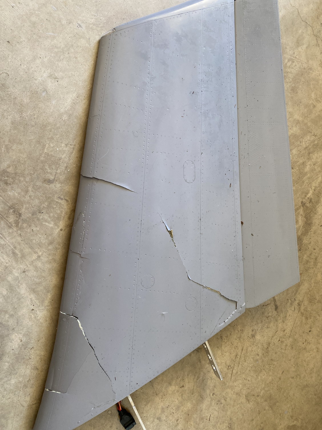
Spent the morning stripping the wreckage and looking for clues, especially in regards to some form of structural failure.
All control surfaces were still attached and linkages intact and able to move freely. Servos felt smooth, but have not been powered to check if they still work.The rear fuselage bulkhead that holds the elevator servo had fractured in multiple places and allowed the elevator servo to come loose, but I suspect that was a result of the impact.
Both flaperons and the left inner flap are undamaged. The tailplane has one minor crack in the upper fairing, but is otherwise undamaged.
The left wing was virtually undamaged, with just the loss of the last 1" on the trailing edge at the wing tip. No structural damage was observed. After loosening the retaining screws, it slid off the wing joiners easily at the crash site so that we could get it in the car.
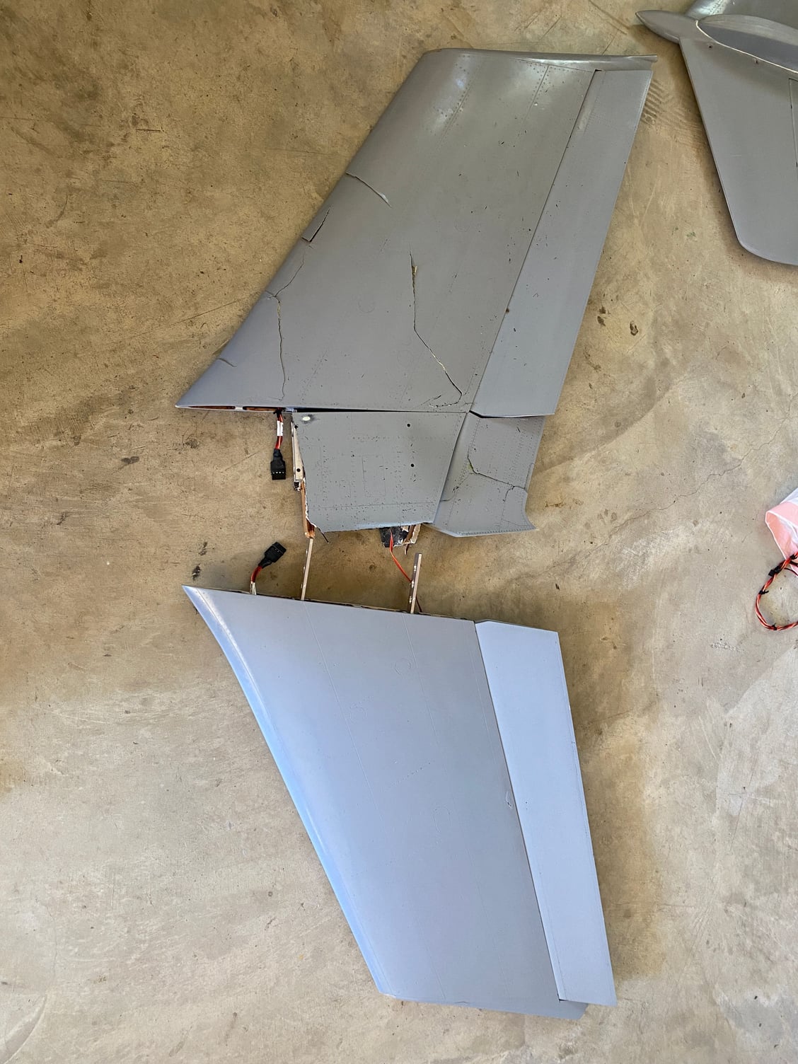
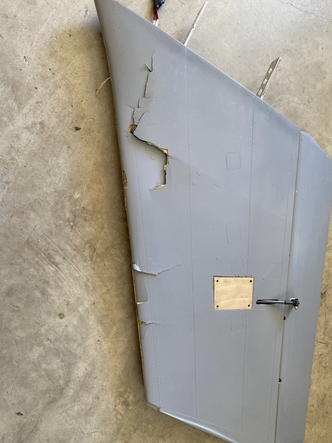
The right wing showed significant damage, and it had separated along with a section of the fuselage, which was easily removed at the wing joiners. The upper and lower skins were cracked in multiple places. On initial inspection it was not possible to tell if the damage was caused in-flight or by the impact.
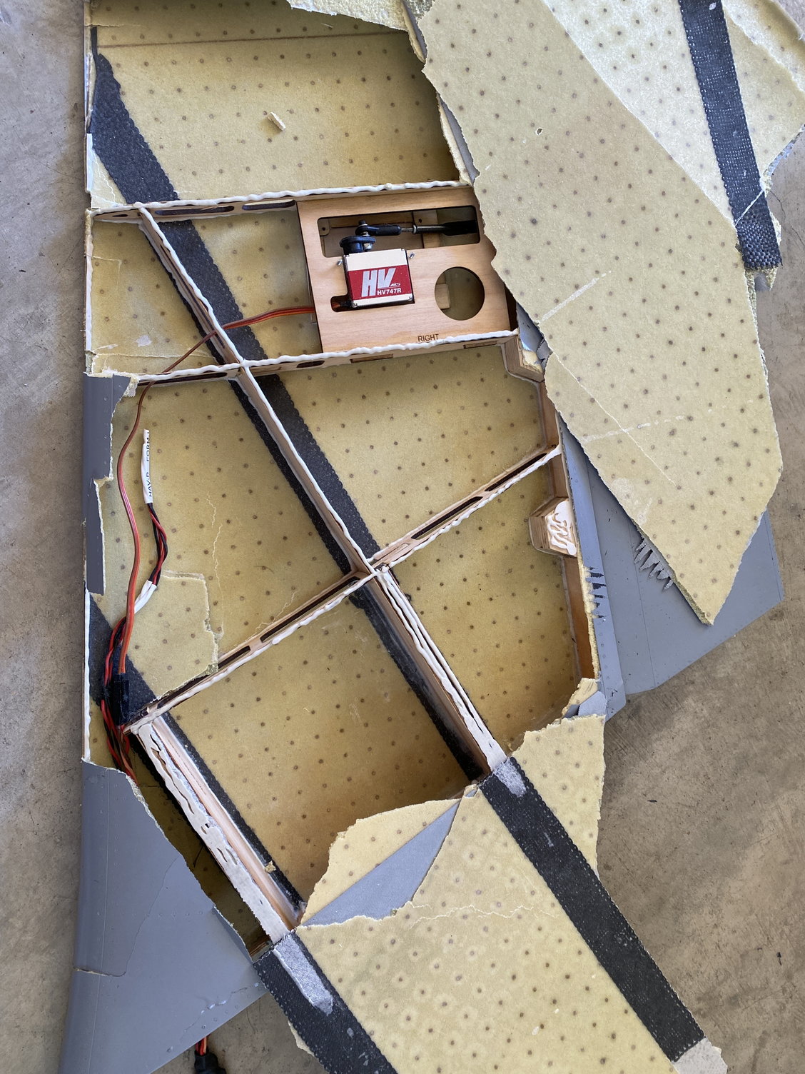
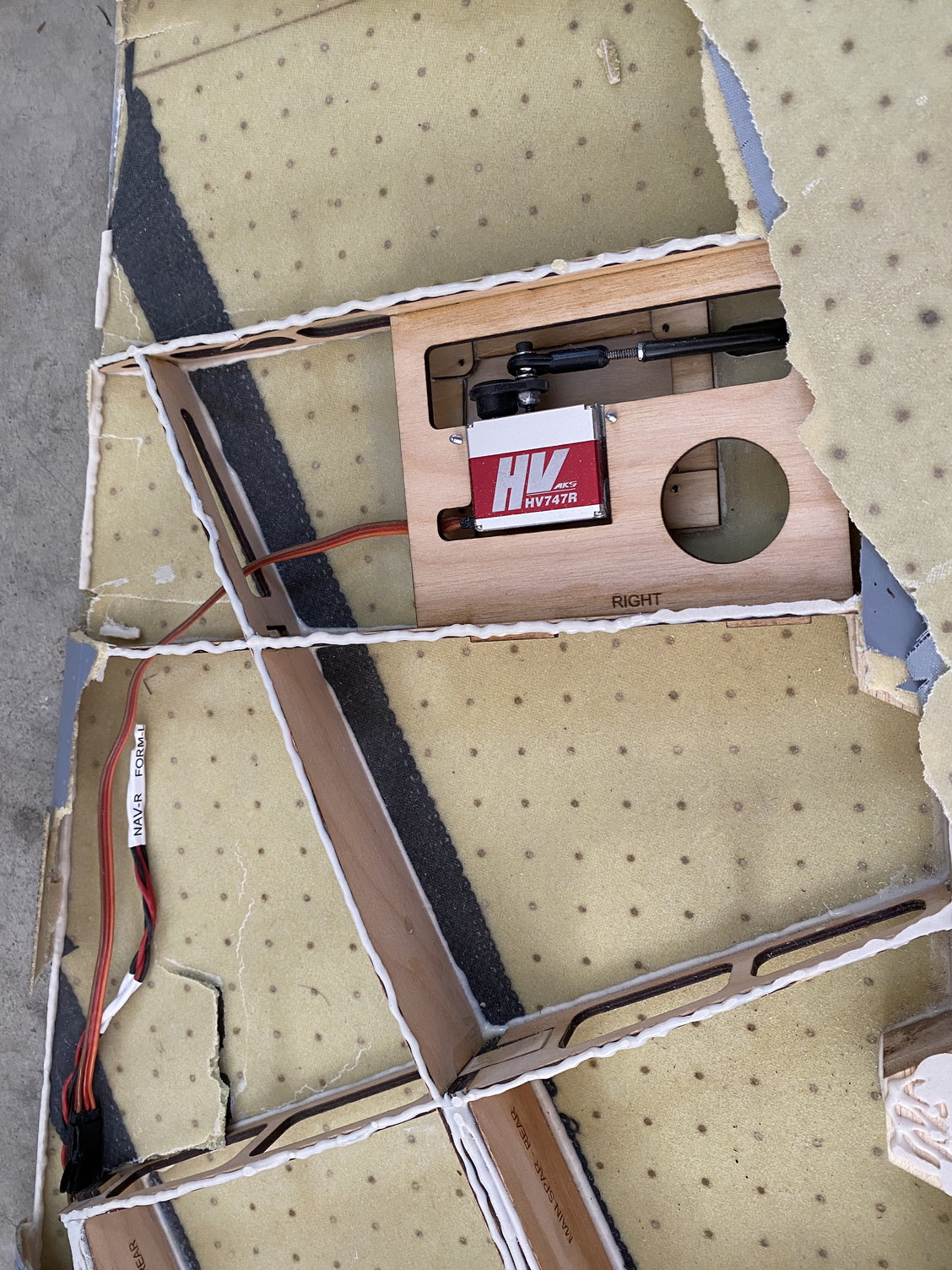
Further checking of the right wing showed that the upper skin was loose and could easily be removed. As I peeled back the skin it became apparent that it was not bonded to the internal structure. The Hysol on the structure showed very little contact with the skin.
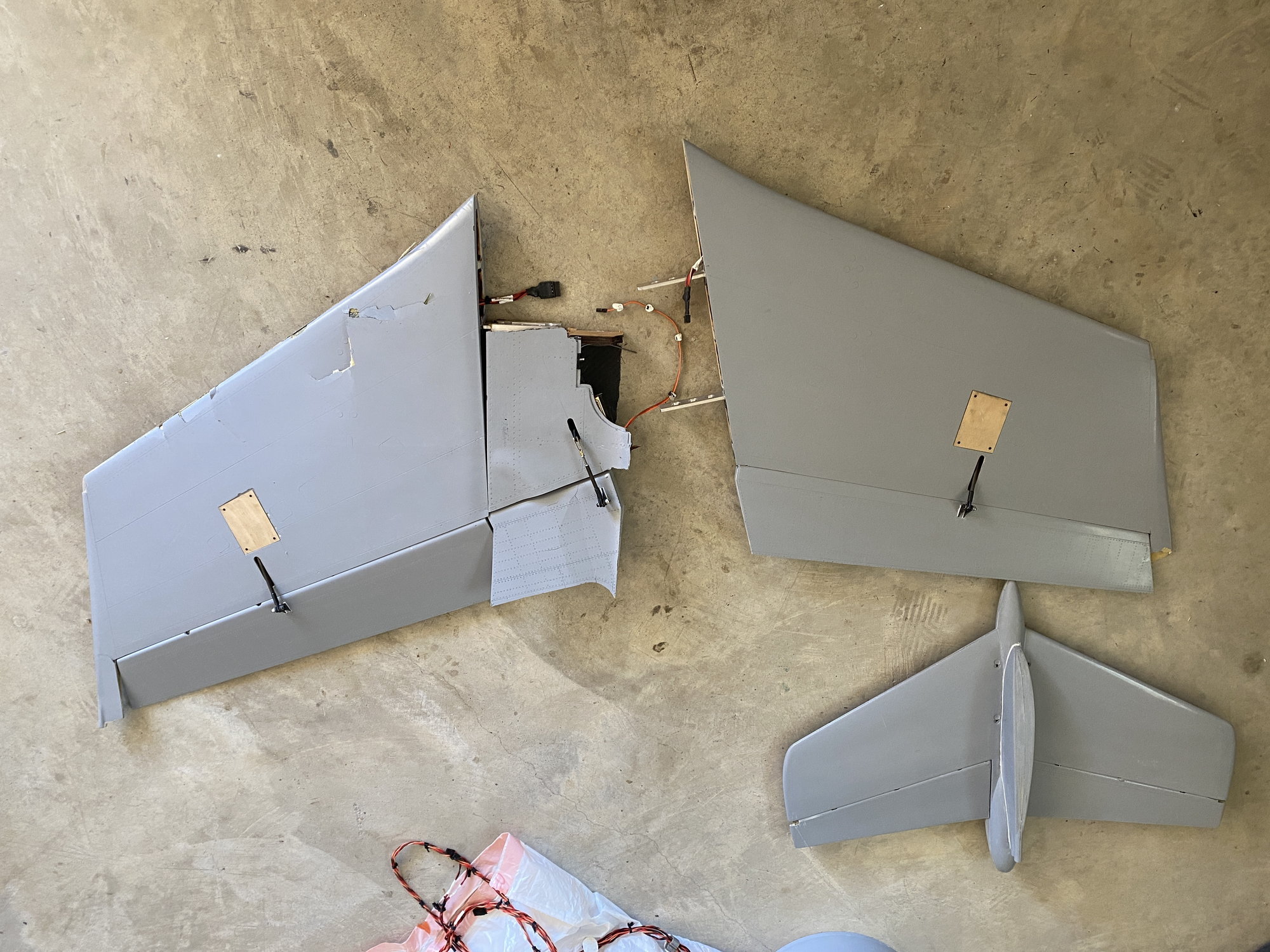
De-skinning the left wing showed that it was firmly attached and in contact in all areas, although the tolerances could be tightened up to reduce the glue thickness.
I feel confident that this lack of upper skin bonding to the internal structure resulted in a loss of torsional rigidity of the right wing. With the 3deg washout, there will be significant torsion acting on the outer wing and this is likely to have caused the right outer wing to fail, probably in a nose down direction, leading to the snap/ spin.
I'm currently not sure if I made an error in generating the internal structure in CAD, or if the built-up wing plugs caused a variation in wing thickness. Probably a combination of both, but it allowed at least a 1.5mm gap between the top of the structure and the upper skin across most of the structure, both ribs and spars. I had bonded the structure to the lower skin first and confirmed it was seated correctly, but it is really hard to check the closed structure once the top skin is down.
No one to blame apart from myself.......
Paul
All control surfaces were still attached and linkages intact and able to move freely. Servos felt smooth, but have not been powered to check if they still work.The rear fuselage bulkhead that holds the elevator servo had fractured in multiple places and allowed the elevator servo to come loose, but I suspect that was a result of the impact.
Both flaperons and the left inner flap are undamaged. The tailplane has one minor crack in the upper fairing, but is otherwise undamaged.
The left wing was virtually undamaged, with just the loss of the last 1" on the trailing edge at the wing tip. No structural damage was observed. After loosening the retaining screws, it slid off the wing joiners easily at the crash site so that we could get it in the car.
The right wing showed significant damage, and it had separated along with a section of the fuselage, which was easily removed at the wing joiners. The upper and lower skins were cracked in multiple places. On initial inspection it was not possible to tell if the damage was caused in-flight or by the impact.
Further checking of the right wing showed that the upper skin was loose and could easily be removed. As I peeled back the skin it became apparent that it was not bonded to the internal structure. The Hysol on the structure showed very little contact with the skin.
De-skinning the left wing showed that it was firmly attached and in contact in all areas, although the tolerances could be tightened up to reduce the glue thickness.
I feel confident that this lack of upper skin bonding to the internal structure resulted in a loss of torsional rigidity of the right wing. With the 3deg washout, there will be significant torsion acting on the outer wing and this is likely to have caused the right outer wing to fail, probably in a nose down direction, leading to the snap/ spin.
I'm currently not sure if I made an error in generating the internal structure in CAD, or if the built-up wing plugs caused a variation in wing thickness. Probably a combination of both, but it allowed at least a 1.5mm gap between the top of the structure and the upper skin across most of the structure, both ribs and spars. I had bonded the structure to the lower skin first and confirmed it was seated correctly, but it is really hard to check the closed structure once the top skin is down.
No one to blame apart from myself.......
Paul
Last edited by JSF-TC; 10-22-2021 at 09:56 AM.
10-22-2021, 10:31 AM
#675
Paul
We are all gutted for you, but at least you found the very likely cause. I’m surprised handling the wing did not exhibit a ‘drum’ sound. I twist and flex even well known manufacturers wings looking for something. I continue to do this through a models life as flight and transport shocks can loosen even a good joint. A guy in the local club had a 3m aerobatic model and the top skin had no glue on the structure within the wing, just the seams were glued!
How does the saying go…3rd time lucky